Vehicle integrated control system

Inactive Publication Date: 2007-06-21
TOYOTA JIDOSHA KK
View PDF2 Cites 25 Cited by
  • Summary
  • Abstract
  • Description
  • Claims
  • Application Information

AI Technical Summary

Benefits of technology

[0021] According to the present invention, for example, when the driver suddenly presses down the accelerator pedal, the braking force by the brake system control unit is quickly decreased, a torque generated from the engine or a drive motor in the driving system control unit is rapidly increased, and the gear ratio is shifted down to a level allowing generation of a high torque. Under such integrated control, fuel efficiency may be lowered to a level outside an optimal fuel consumption range of the engine, or lowering of drivability may be caused due to excessive acceleration. In spite of such disadvantages, priority can be placed on a time for attaining the control target requested by the driver. On the other hand, when the driver suddenly presses down the brake pedal, the driving force by the driving system control unit is rapidly decreased, while the braking torque by a wheel brake in the brake system control unit is quickly increased. Under such integrated control, running energy may be converted to thermal energy at the wheel brake, and energy efficiency may be lowered. In spite of such disadvantages, priority can be placed on a time for attaining the control target requested by the driver. In the case of a vehicle equipped with a drive motor, regenerative braking may be achieved using that motor, instead of or in addition to the wheel brake.
[0025] According to the present invention, when the driver presses down the brake pedal, for example, control is exerted such that power generation by a regenerative braking motor (drive motor) in the driving system control unit is maximized. Here, use of increase in the braking torque from the wheel brake in the brake system control unit in which energy cannot be recovered is avoided as much as possible, in a range satisfying the braking force requested by the driver. Under such integrated control, running energy that has conventionally been converted to thermal energy by the wheel brake in the brake system control unit can be recovered in the driving system control unit, thereby energy efficiency being improved.
[0029] According to the present invention, such a situation that a vehicle is currently running before a corner, and the vehicle will decelerate for entering the corner in the near future and re-accelerate at the exit of the corner is sensed as the environmental information. An optimal braking / driving force is calculated in advance based on such information on the surroundings of the vehicle in the future and the driving system control unit and the brake system control unit are controlled in an integrated manner, so that the optimal braking / driving force can be generated.

Problems solved by technology

The effect produced by each of the different types of motion control devices may not always emerge in a manner independent of each other at the vehicle.
There is a possibility of mutual interference.
In the case of developing a plurality of types of motion control devices in the aforesaid manner, organization of the interaction and coordination between respective motion control devices requires much time and effort.
This scheme involves the problem of how the contention among the plurality of motion control devices, when required to operate the same actuator at the same time, is to be resolved.
In the above-described case where the interaction and coordination among a plurality of motion control devices are to be organized in a supplemental or additional manner after the motion control devices are developed independently of each other, it is difficult to solve the problem set forth above proficiently.

Method used


Image

  • Vehicle integrated control system
  • Vehicle integrated control system
  • Vehicle integrated control system

Examples


Embodiment Construction

[0048] An embodiment of the present invention will be described hereinafter with reference to the drawings. The same elements have the same reference characters allotted. Their label and function are also identical. Therefore, detailed description thereof will not be repeated.

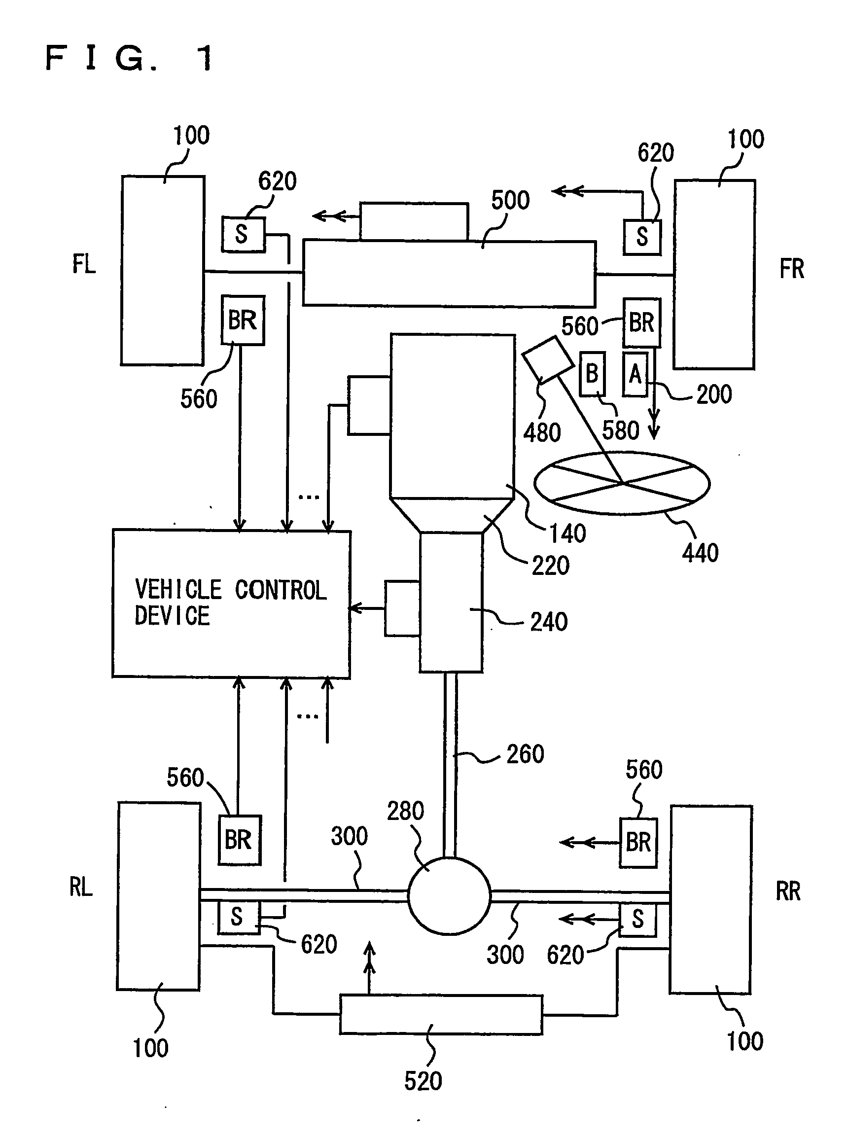
[0049] Referring to the block diagram of FIG. 1, a vehicle integrated control system according to an embodiment of the present invention has an internal combustion engine incorporated in a vehicle as a driving power source. The driving power source is not restricted to an internal combustion engine, and may be an electric motor alone, or a combination of an engine and an electric motor. The power source of the electric motor may be a secondary battery or a cell.

[0050] The vehicle includes wheels 100 at the front and back of respective sides. In FIG. 1, “FL” denotes a front-left wheel, “FR” denotes a front-right wheel, “RL” denotes a left-rear wheel, and “RR” denotes a rear-right wheel.

[0051] The vehicle inco...


PUM


Abstract

An integrated control system includes a main control system (accelerator) controlling a driving system, a main control system (brake) controlling a brake system, and a main control system (steering) controlling a steering system, based on manipulation by a driver, as well as an adviser unit generating and providing information to be used at each main control system based on environmental information around a vehicle or information related to a driver. The advisor unit executes a program including the steps of: sensing a vehicle state, driver's manipulation, and environmental information; operating an expected value by the driver with regard to a driving force; performing distribution processing of a braking / driving torque; and operating a distribution ratio so as to carry out distribution.

Description

TECHNICAL FIELD [0001] The present invention relates to a system controlling a plurality of actuators incorporated in a vehicle, and more particularly, a system controlling in an integrated manner a plurality of actuators with the possibility of mutual interference. BACKGROUND ART [0002] There has been an increasing trend in recent years towards incorporating many types of motion control devices in the same vehicle to control the motion of the vehicle. The effect produced by each of the different types of motion control devices may not always emerge in a manner independent of each other at the vehicle. There is a possibility of mutual interference. It is therefore important to sufficiently organize the interaction and coordination between respective motion control devices in developing a vehicle that incorporates a plurality of types of motion control devices. [0003] For example, when it is required to incorporate a plurality of types of motion control devices in one vehicle in the ...

Claims


Application Information

Patent Timeline
IPC IPC(8): B62D6/00B60R16/02B60R21/00B60T8/00B60W10/00B60W10/04B60W10/06B60W10/08B60W10/10B60W10/18B60W10/20B60W30/00B60W50/04B60W50/14B60W50/16F02D29/02G08G1/16
CPCB60K41/202Y02T90/162B60K2741/205B60K2741/283B60L7/18B60L11/1816B60L2240/16B60L2240/62B60L2250/26B60W10/04B60W10/18B60W10/20B60W30/00B60W40/02B60W40/08B60W40/10B60W2520/105B60W2540/10B60W2540/12B60W2550/20B60W2550/402Y02T10/7005Y02T10/7291Y02T90/14Y02T90/16B60K41/282B60W2554/00B60W2556/50Y02T10/72B60R16/00B60R16/02B60T8/00B60W40/00Y02T10/70Y02T10/7072
Inventor TAKAMATSU, HIDEKITOKURA, TAKAAKI
Owner TOYOTA JIDOSHA KK
Why Eureka
Try Eureka