
Apparatus and method for measuring the position of a member

Inactive Publication Date: 2007-06-21
HONEYWELL INT INC
View PDF4 Cites 15 Cited by
  • Summary
  • Abstract
  • Description
  • Claims
  • Application Information

AI Technical Summary

Benefits of technology

[0009] It is a further aspect of the present invention to provide for a low cost apparatus for measuring the position of a member.
[0010] It is an additional aspect of the present invention to provide for an apparatus for measuring the position of a member which can be more easily integrated into existing applications
[0014] Advantageously, the sonic delay line is of low cost and unsusceptible to wear & tear as the transducer is operable without contacting the sonic waveguide so that the sonic delay line has a long operating life. Furthermore, the displacement range of the sonic delay line is long and the response time is low allowing for measurement of the position of fast moving members, such as pistons with fast stroke speeds. The sonic delay line is less complex and exhibits low hysteresis and high signal to noise ratio (SNR) than existing positions sensors.
[0015] The generator can be an actuator, such as for example a piezo-electric actuator, coupled to a distal end of the sonic wave guide. The transducer can be a biasing magnetic source and coil. The oil assembly can acts as a pick-up for applying a magnetic field to the sonic wave guide at the second position and a coil for detecting a change in magnetic flux density at the second position caused by the sonic wave(s). Utilizing a piezo-electric actuator permits generation of the sonicwaves in a simple manner without providing additional current pulses in the sonicwave guide so that the sonic wave line can be made more compact and at a lower cost.
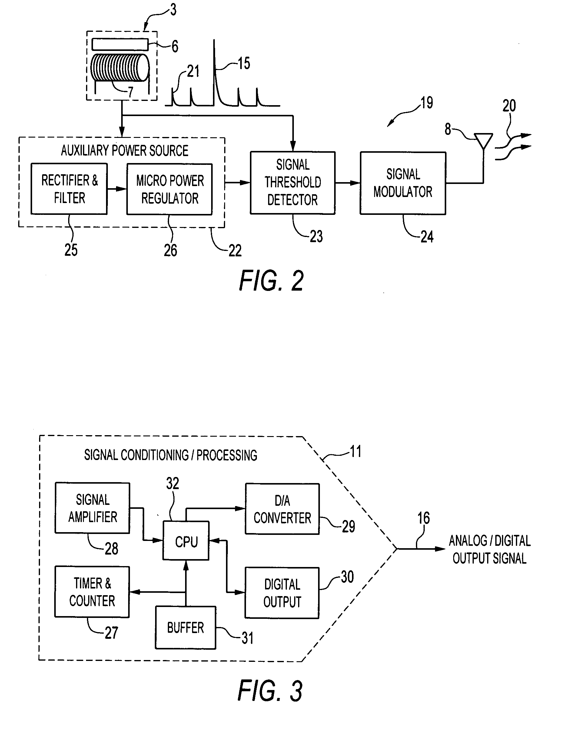
[0021] Advantageously, the excitation sonic waves are converted to electrical power for powering an electronic device, such as the transmitter, so that the device is effectively self-powered, without the need of local batteries or an external power supply.

Problems solved by technology

Contact type linear position sensors for measuring the position of members, such as for example, potentiometer based position sensors in which a wiper brushes over the surface of a resistive element, suffer from a variety of drawbacks including a reduced product life, sensitivity to vibration, significant hysteresis and non-linearity, short operating lengths and difficulty in measuring the position of members moving at high speed, such for example high stroke speed pistons.
However, known non-contact linear positions sensor employed in industrial motion control and other applications for measuring the position of cylinders, pistons, bearings and other members are complex in design and costly to produce.
In such position sensors, electronic complexity is dependent on the measuring length.
Furthermore, such sensor systems are susceptible to stray magnetic fields and necessitate application of complex algorithms, in the associated signal conditioning circuitry.
Additionally, the sensor system requires high power consumption and has a response time which is limited by the sampling of the sensing array for signal conditioning.

Method used


Image

  • Apparatus and method for measuring the position of a member
  • Apparatus and method for measuring the position of a member
  • Apparatus and method for measuring the position of a member

Examples


Embodiment Construction

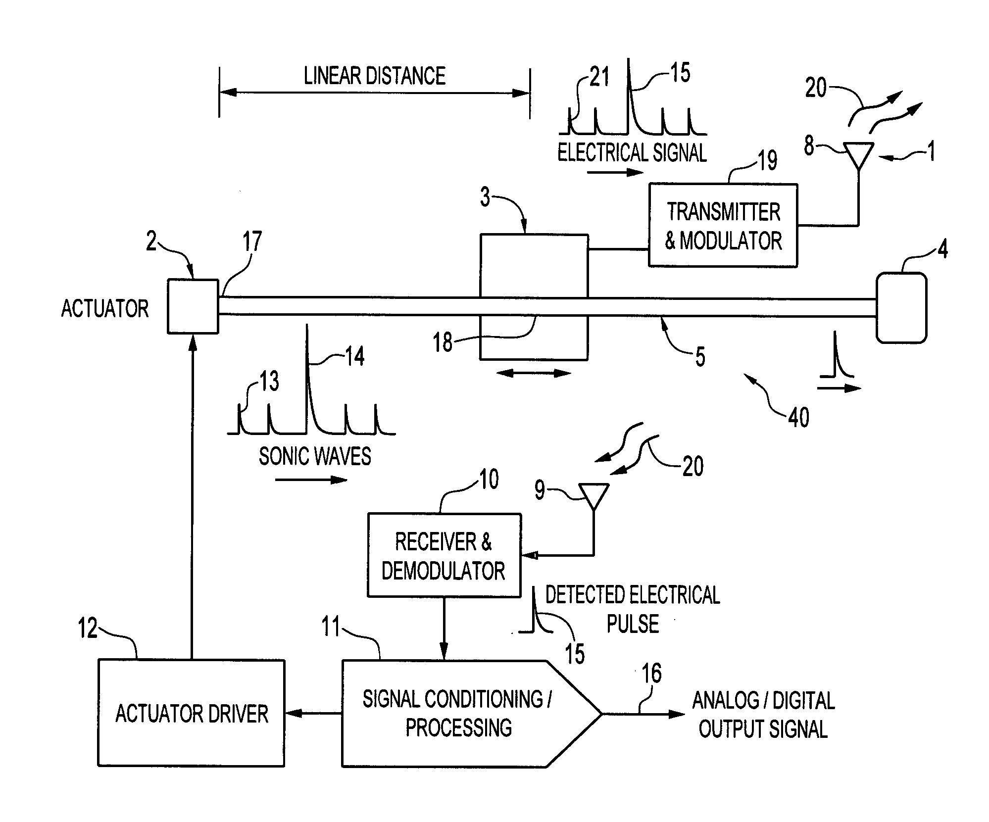
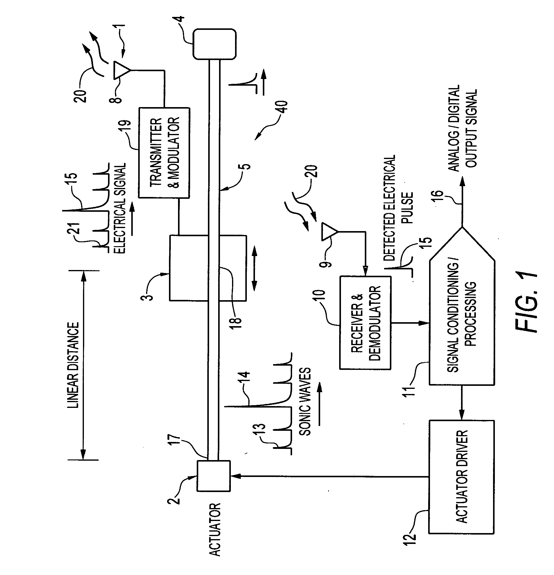
[0033] Referring to FIG. 1 of the accompanying drawings, which illustrates a block diagram of an apparatus for measuring the position of a member according to one embodiment, the apparatus 1 has a sonic wave actuator or generator 2, operatively coupled to a sonic wave guide 5 for generating sonic waves 13,14 at a first position 17, and a non-contact transducer 3, operatively coupled to the sonic wave guide, for converting the sonic waves 13,14 at a second position 18 into electrical signals. Generator 2, wave guide 5 and transducer 3 collectively form a sonic delay line 40.

[0034] The sonic waves 13,14 travel mechanically in the waveguide away from the first position 17 to the second position 18 with a propagation velocity which is determined by the waveguide material so that the time delay between generating and detecting the sonic waves 13, 14 at the first and second positions 17,18, respectively, represents the distance between the first and second positions. This distance can be...


PUM


Abstract

An apparatus and method for measuring the position of a member. The apparatus has a sonic waveguide, a generator for generating an interrogation sonic wave at a first position in the sonic wave guide, and a transducer for converting the interrogation sonic wave, at a second position in the sonic wave guide, to an interrogation signal. A timer can be enabled in response to the generator generating the interrogation sonic wave and stopped in response to the transducer converting the interrogation sonic wave so as to determine the propagation time delay of the interrogation sonic wave and the distance between the first and second positions. When the transducer is attached to a member, the position of the member can be determined from this distance. The apparatus can include a transmitter for transmitting the interrogation signal. The generator can be configured to generate an excitation sonic wave which is converted by the transducer to a power signal for powering the transmitter.

Description

TECHNICAL FIELD [0001] Embodiments are generally related to measurement apparatus and, more particularly, to apparatus and methods for measuring the position of a member or medium. Additionally, embodiments are related to sonic delay lines for sensing the linear position of a member and methods of sensing associated therewith. BACKGROUND [0002] Contact type linear position sensors for measuring the position of members, such as for example, potentiometer based position sensors in which a wiper brushes over the surface of a resistive element, suffer from a variety of drawbacks including a reduced product life, sensitivity to vibration, significant hysteresis and non-linearity, short operating lengths and difficulty in measuring the position of members moving at high speed, such for example high stroke speed pistons. [0003] Non-contact type position sensors are advantageous for making position measurements because position changes of the member can be made without causing wear and tear...

Claims


Application Information

Patent Timeline
IPC IPC(8): H03H9/00
CPCG01D5/485
Inventor MUNIRAJU, RAGHAVENDRASADASIVAN, SARAVANANTHOTADAKUMBRI, RAVIPRAKASH
Owner HONEYWELL INT INC
Learn More