
Method and apparatus for controlling reactions

Inactive Publication Date: 2007-06-14
SCHEMBRI CAROL T
View PDF25 Cites 13 Cited by
  • Summary
  • Abstract
  • Description
  • Claims
  • Application Information

AI Technical Summary

Benefits of technology

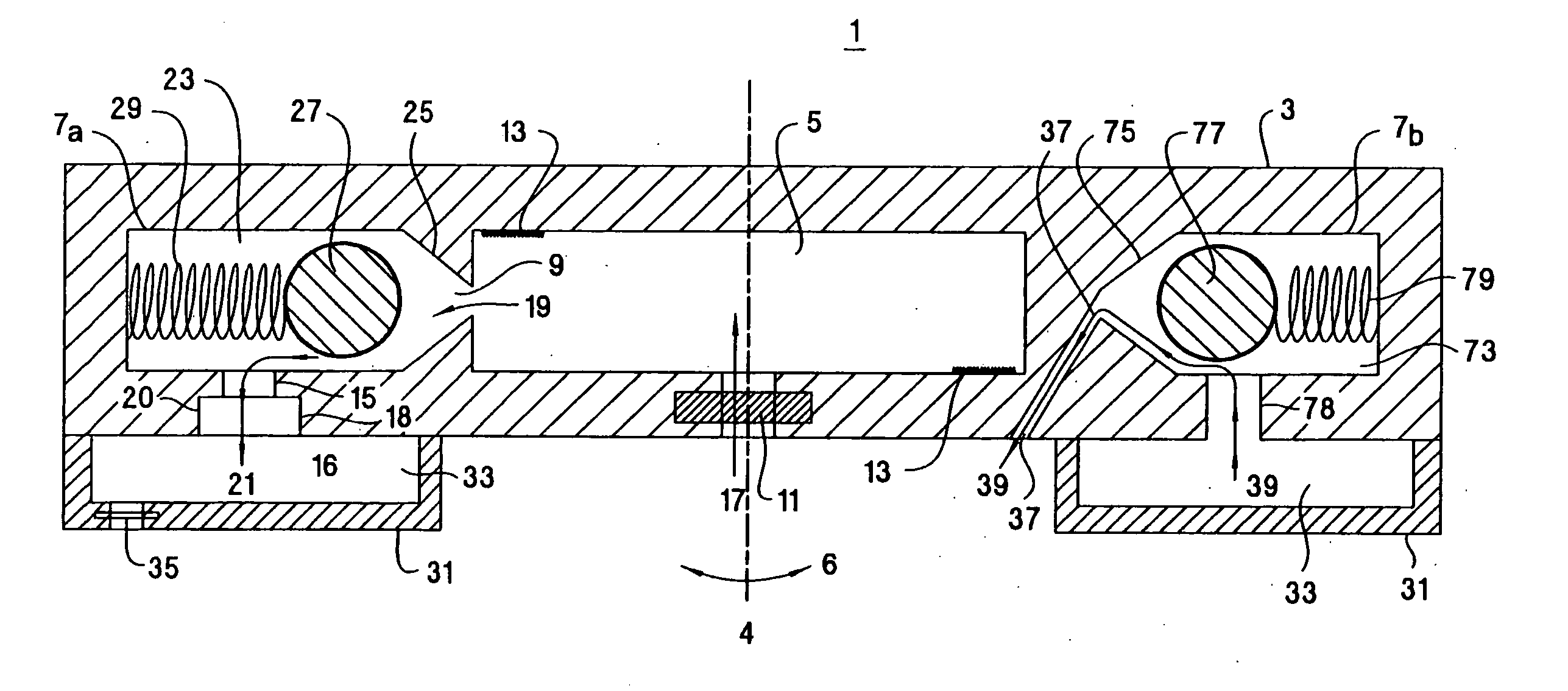
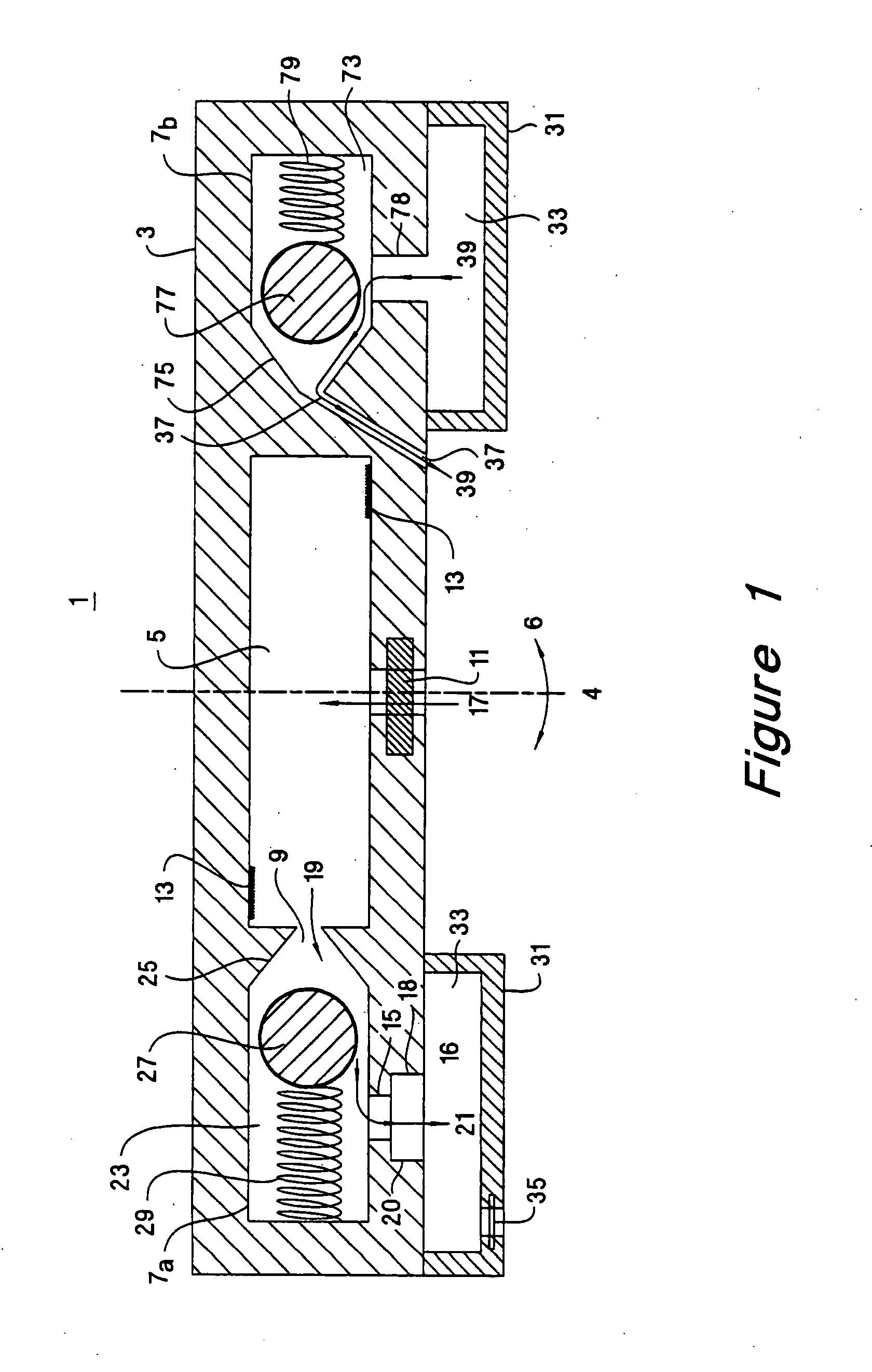
[0012] The invention provides an analytical device incorporating a centrifugal force-activated valve for controlling reactions and for moving fluid within the analytical device. The centrifugal force-activated valve allows for several fluids to be passed through the analytical device and allows the analytical device to be used for multiple serial reactions. The centrifugal force-activated valve provides simple and reliable control over fluid movement and can be tuned to open or close over a wide range of rotational speeds.
[0017] The analytical substrate can be made transparent to optical detection means external to the housing enclosure. A transparent analytical substrate allows for an assay of the active surface by scanning the active surface through the analytical substrate using the optical detection means.

Problems solved by technology

However, the disadvantage of differential flow is that the entire volume of fluid is never completely controlled.
The disadvantage with siphons is that some of the fluid is lost in the entrance of the siphon and that great care must be taken to prevent the siphon from priming prematurely or from losing prime prematurely.
Two-axis mechanisms provide better fluid control, but at substantial instrumentation cost, complexity, and size.

Method used


Image

  • Method and apparatus for controlling reactions
  • Method and apparatus for controlling reactions
  • Method and apparatus for controlling reactions

Examples


Embodiment Construction

[0033] In the following detailed description and in the several figures of the drawings, like elements are identified with like reference numerals.

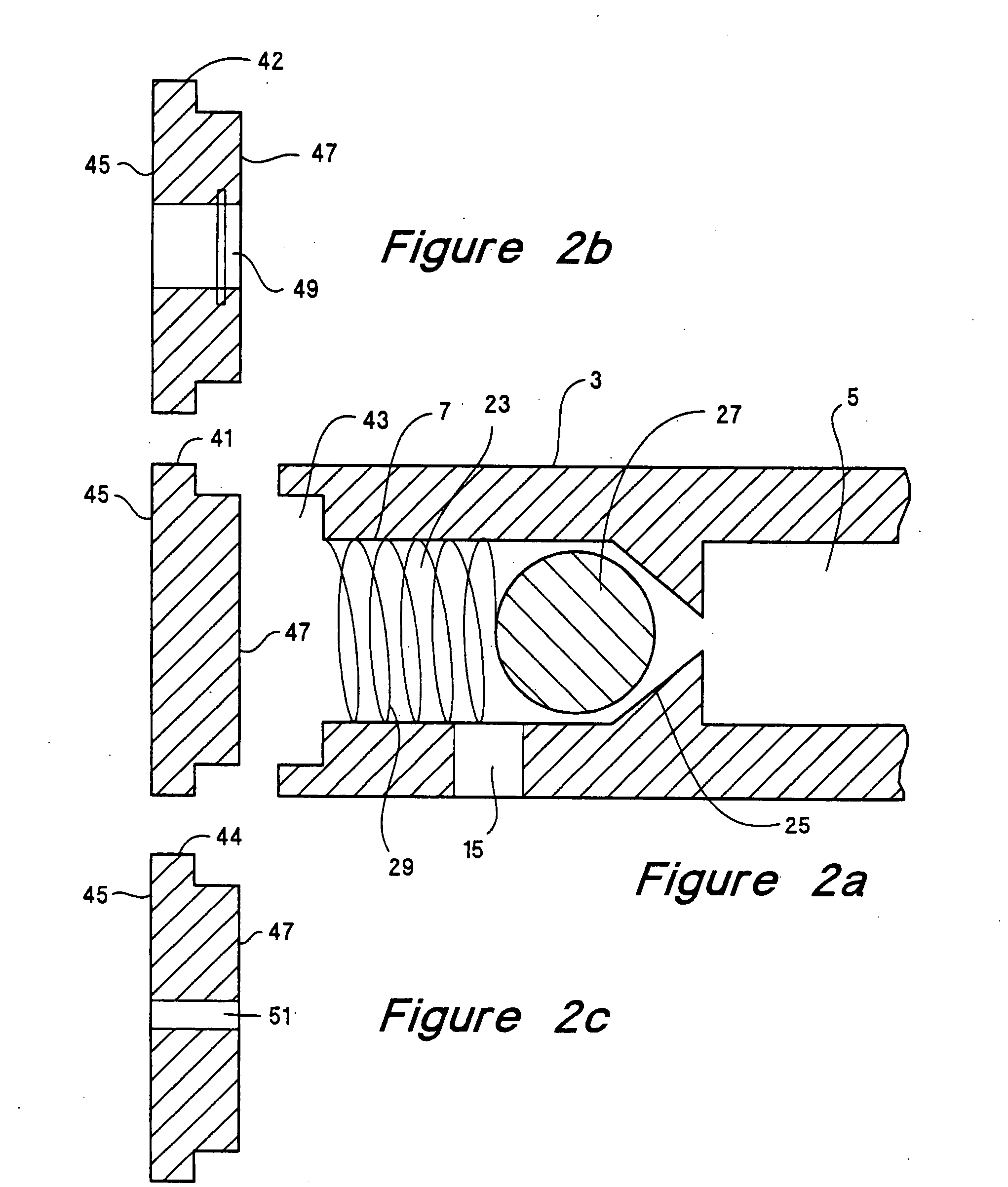
[0034] As shown in the drawings for purposes of illustration, the invention is embodied in an analytical device having an assay chamber for fluid reactions and at least one centrifugal force-activated valve in fluid communication with the assay chamber. The valve provides positive control of fluid contained in the assay chamber and allows for multiple, fluid reaction steps, mixing steps, and washing steps to occur in the assay chamber. The analytical device of the present invention is easy to use, can be manufactured at low cost, is adaptable to automation, provides predictable fluid control that can be tuned over a wide range of rotational speeds, and can be disposed of after use to prevent contamination from repeated use of the same analytical device. Previous apparatus for controlling reactions have incorporated complex fluid control ...


PUM


Abstract

The invention relates to a method and an apparatus for performing an assay on chemical, biochemical, or biological fluids. The apparatus includes an assay chamber for fluid reactions and a centrifugal force activated-valve for controlling fluid movement through the assay chamber. An active surface can be positioned in the assay chamber to react with fluids passed through the assay chamber. The active surface may contain biomolecular probes. The biomolecular probes can be DNA, DNA fragments, RNA, RNA fragments, reagents, protein, protein fragments, lipids, and lipid fragments. The apparatus is particularly useful when multiple reactions, dilutions, or washing steps are required to determine a final answer. The centrifugal force activated-valve provides positive control over fluid in the assay chamber and allows for repeated use of the same chamber for multiple reaction steps. The apparatus can be disposed of after an assay to eliminate potential contamination from reuse of the same apparatus. Fluids passed through the assay chamber may be recovered for subsequent analysis, processing, or reactions.

Description

CROSS-REFERENCE TO RELATED APPLICATIONS [0001] This application is a continuation application of application Ser. No. 09 / 695,008 filed Oct. 23, 2000, which is a divisional of application Ser. No. 09 / 133,102 filed Aug. 12, 1998 (now U.S. Pat. No. 6,162,400). Priority is claimed under 35 U.S.C. 120 from both of the foregoing applications, which are incorporated herein by reference.BACKGROUND OF THE INVENTION [0002] The present invention relates generally to analytical devices for performing assays and more particularly to an analytical device that includes a centrifugal force actuated valve to control fluid and a method of utilizing the analytical device to perform an assay. [0003] There are many analytical methods that require one or more reactions or analytical steps to determine a final answer. Examples are heterogeneous immunochemistry reactions, hybridization of DNA to DNA, and hybridization of DNA to RNA. In order to determine the concentration or presence of an analyte, such an...

Claims


Application Information

Patent Timeline
IPC IPC(8): G01N33/00B01L3/00G01N1/00
CPCB01L3/502B01L2300/0636B01L2300/0877B01L2400/0409Y10T436/2575G01N33/491G01N35/1097Y10T436/111666B01L2400/0633Y10T137/108
Inventor SCHEMBRI, CAROL T.
Owner SCHEMBRI CAROL T
Learn More