Eureka AIR delivers breakthrough ideas for toughest innovation challenges, trusted by R&D personnel around the world.

Communication handover method, communication handover program, and communication system

Inactive Publication Date: 2007-06-14
PANASONIC CORP
View PDF6 Cites 15 Cited by
  • Summary
  • Abstract
  • Description
  • Claims
  • Application Information

AI Technical Summary

Benefits of technology

[0032] Further, there is a problem such that every time the MN 10 is about to do the L2 handover, the AR 21 needs to perform the process of the step S603, and an RtSolPr message and a PrRtAdv message are to be transmitted and received between the MN 10 and the AR 21. That is, at the time of the L2 handover by the MN 10, an increment in the load of a process in the AR 21 and an increment in communication traffic between the MN 10 and the AR 21 occur. In particular, when a plurality of APs 22, 23 having narrow radio coverage areas are under the control of the AR 21, and in an environment where there are multiple MNs 10 which repeat movements frequently, a considerable load is applied to the AR 21, and communication traffic between the MN 10 and the AR 21 significantly increases.
[0082] The invention provides a communication handover method, a communication handover program and a communication system which have the above-described structures, thereby realizing an efficient handover by reducing loads on an MN and an AR and communication traffics thereof while maintaining a packet loss rate improved by the fast handover technology.

Problems solved by technology

The above-described fast handover technology, however, has the following first to third problems.
If the timing of the L2 handover meets the following case (1) or (2), the fast handover is not properly completed, so that reduction in the packet loss rate that is the object of the fast handover technology cannot be accomplished.

Method used


Image

  • Communication handover method, communication handover program, and communication system
  • Communication handover method, communication handover program, and communication system
  • Communication handover method, communication handover program, and communication system

Examples


Embodiment Construction

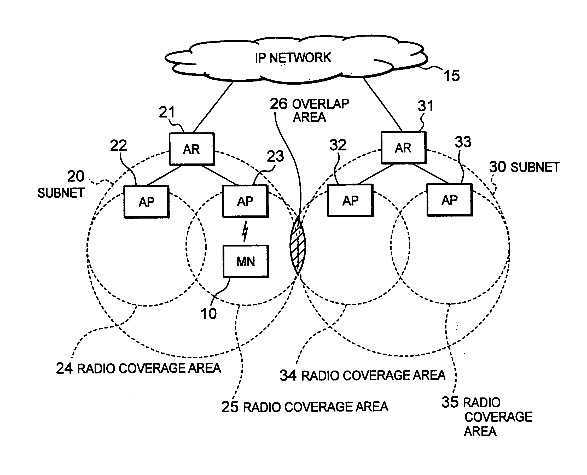
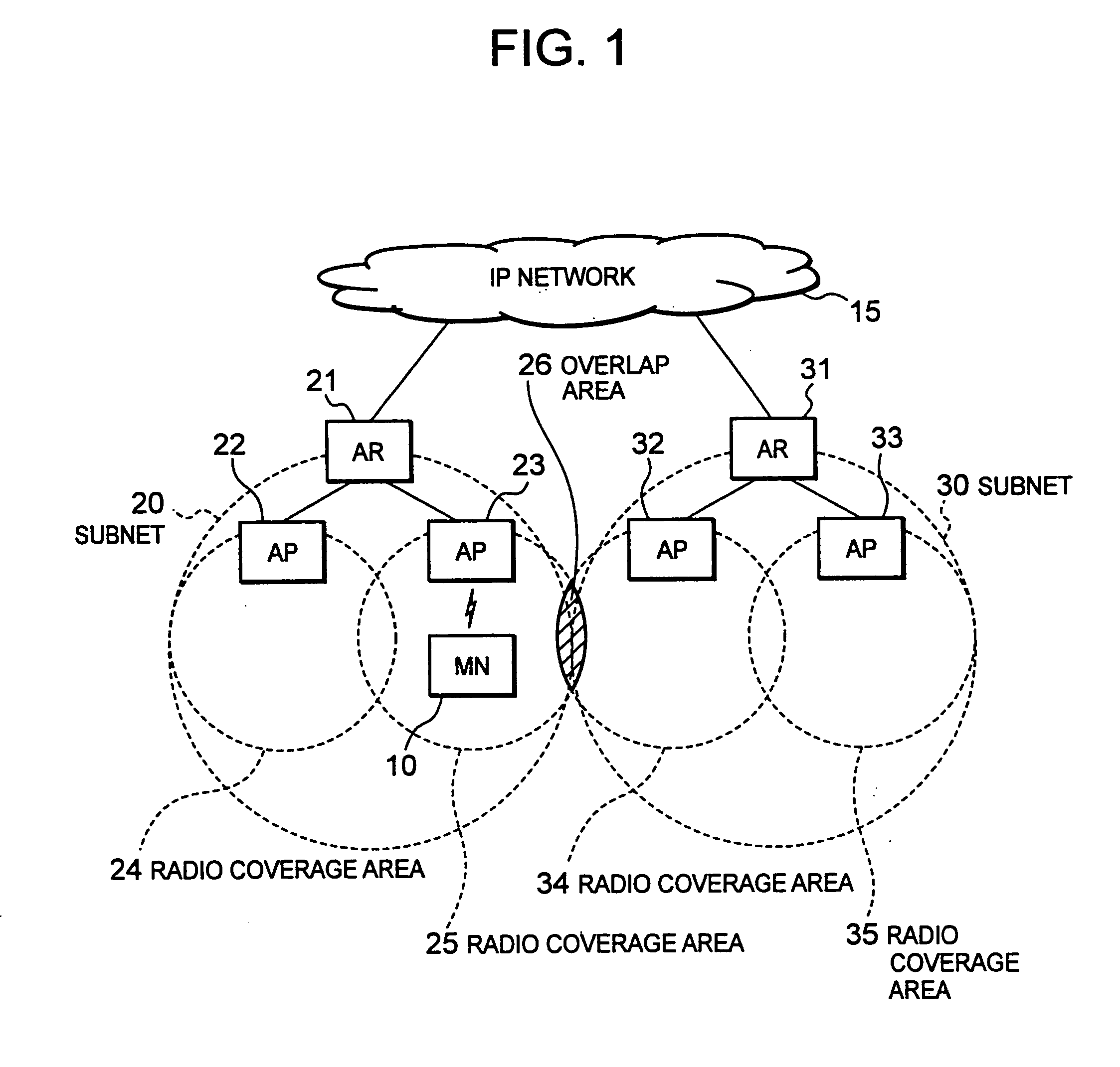
[0089] An embodiment of the invention will now be described with reference to FIGS. 1 to 5. FIG. 1 is an exemplary diagram showing the structure of a radio communication system common to the present invention and the conventional technique, and the structure of the radio communication system shown in FIG. 1 has been explained in the description of the conventional technique. The radio communication system shown in FIG. 1 is referred to in the description of the embodiment of the invention.

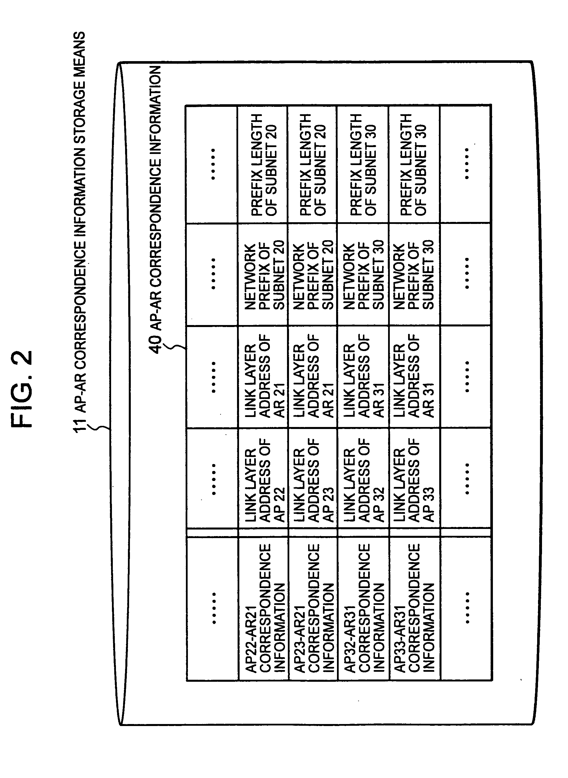
[0090]FIG. 2 is an exemplary diagram showing one example of AP-AR correspondence information which is stored in an MN according to an embodiment of the invention. A significant difference between the invention and the conventional technique lies in that an MN of the invention has AP-AR correspondence information storage means 11 for storing AP-AR correspondence information 40. An MN 10 need not be provided with a special information storage medium as the AP-AR correspondence information storage me...


PUM


Abstract

A technique which realizes an efficient handover by reducing loads on a mobile node and an access router and communication traffics thereof while keeping a packet loss rate in a fast handover technology is disclosed, and according to that technique, a mobile node (MN 10) has a correspondence relationship between information (link layer address of an AP) on an access point (AP 22, 23, 32, 33) and information (link layer address of an AR, and a network prefix and a prefix length of a subnet 20, 30 to which the AR belongs) on an access router (AR 21, 31) having control over the AP, and, by referring to the correspondence relationship, generates an NCoA of a subnet which is the destination of movement in L2 handover between different subnets, does not change an NCoA and executes only the L2 handover in the L2 handover in the same subnet, and performs a conventional fast handover when there is no correspondence relationship relating to an AP at the destination of the L2 handover.

Description

TECHNICAL FIELD [0001] The present invention relates to a communication handover method, a communication handover program, and a communication system that speeds up the handover of a mobile terminal (mobile node) which carries out radio communication, and more particularly, to a technology that speeds up a handover at a mobile node which carries out radio communication using the mobile IPv6 (Mobile Internet Protocol version 6) protocol that is the next generation Internet protocol. BACKGROUND ART [0002] As a technology which provides a user who accesses a communication network like the Internet through a radio network from a mobile node while moving with seamless connection to the communication network, one which uses the mobile IPv6 as the next generation Internet protocol becomes popular. A radio communication system which uses the mobile IPv6 will be explained with reference to FIG. 1. The technology regarding the mobile IPv6 which will be explained below is disclosed in, for exa...

Claims


Application Information

Patent Timeline
IPC IPC(8): H04Q7/00H04L12/56H04L29/06H04W8/08H04W8/26H04W36/00H04W36/08H04W36/10H04W36/22H04W80/00H04W80/04
CPCH04W8/085H04W8/26H04W36/0011H04W36/0016H04W80/00H04W80/04H04W36/0019
Inventor HORI, TAKAKOASOU, KEIGO
Owner PANASONIC CORP
Why Eureka
Eureka Blog
Learn More