
Alignment layer rubbing apparatus

a technology of alignment layer and rubbing surface, which is applied in the direction of grinding machine components, manufacturing tools, instruments, etc., can solve the problems of degrading the display quality of lcd, and achieve the effect of preventing a defect from occurring

Inactive Publication Date: 2007-06-14
BOE HYDIS TECH
View PDF1 Cites 29 Cited by
  • Summary
  • Abstract
  • Description
  • Claims
  • Application Information

AI Technical Summary

Benefits of technology

[0011] Accordingly, the present invention has been made to solve the above-mentioned problems occurring in the prior art, and an object of the present invention is to provide an alignment layer rubbing apparatus capable of preventing a defect from occurring on an alignment layer in a continuous line pattern due to an alien substance during an alignment layer rubbing process.

Problems solved by technology

This degrades the display quality of the LCD.

Method used


Image

  • Alignment layer rubbing apparatus
  • Alignment layer rubbing apparatus
  • Alignment layer rubbing apparatus

Examples


Embodiment Construction

[0020] Hereinafter, a preferred embodiment of the present invention will be described with reference to the accompanying drawings. In the following description and drawings, the same reference numerals are used to designate the same or similar components, and so repetition of the description on the same or similar components will be omitted.

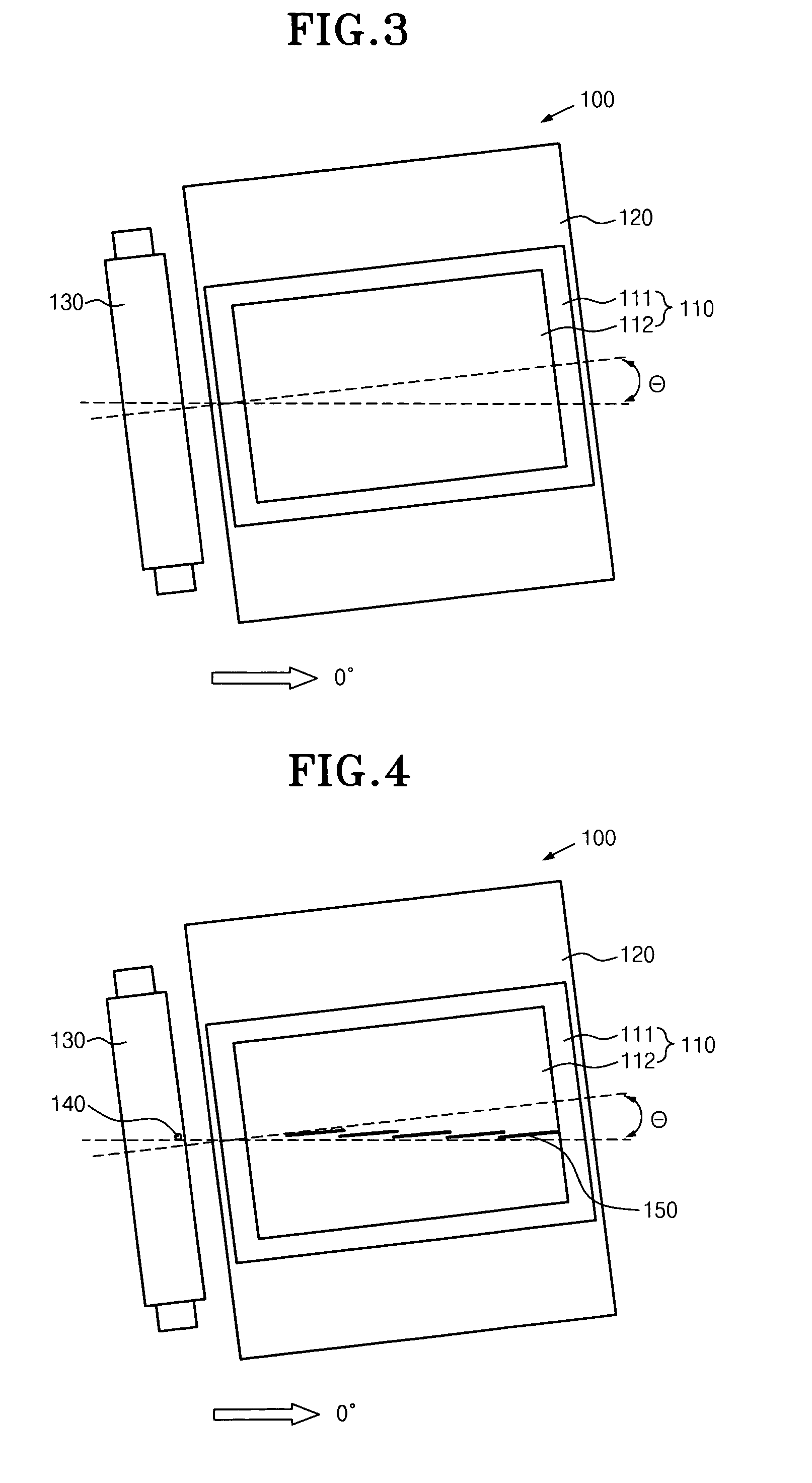
[0021]FIG. 3 is a block diagram briefly showing an alignment layer rubbing apparatus according to an embodiment of the present invention.

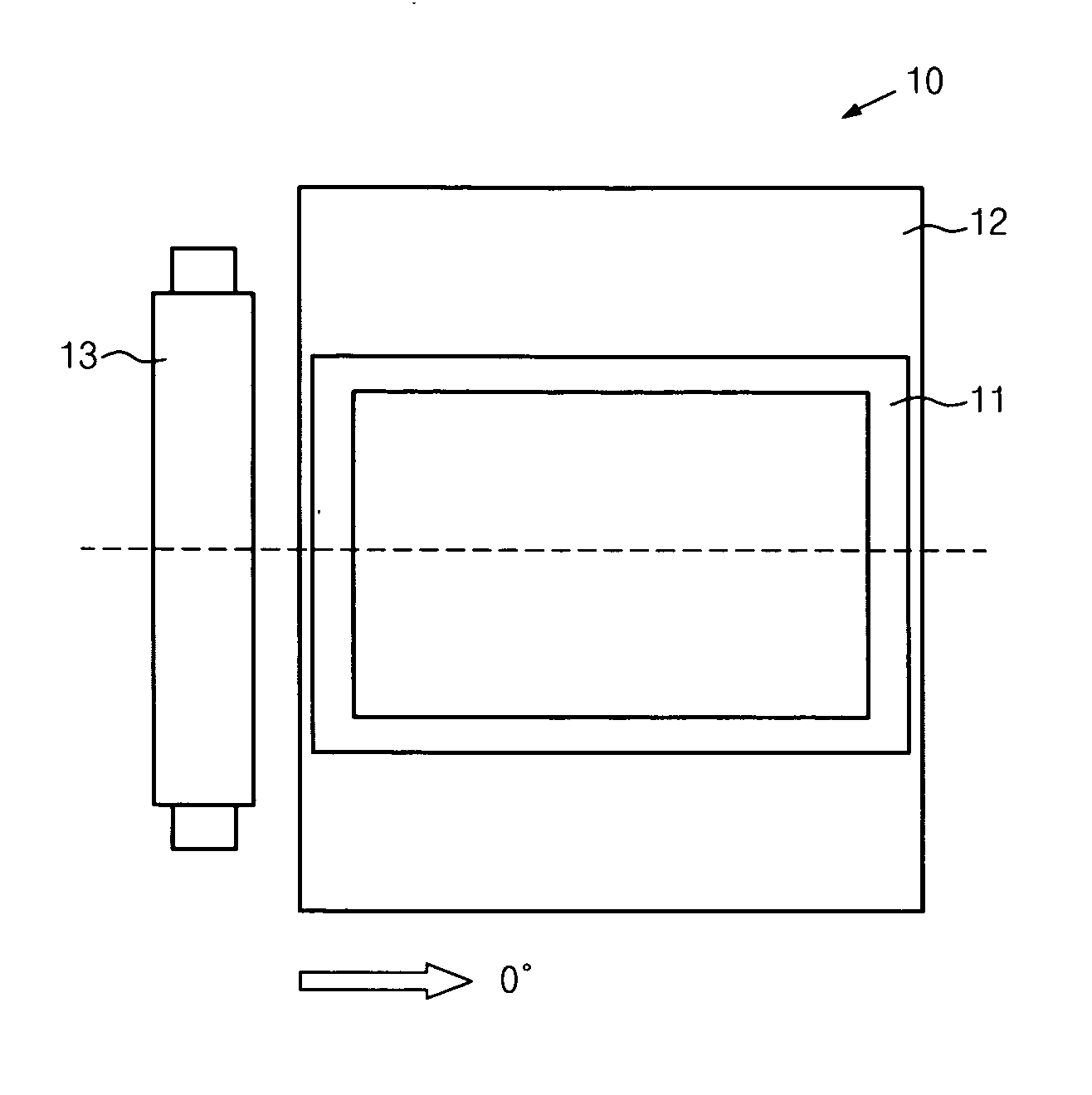
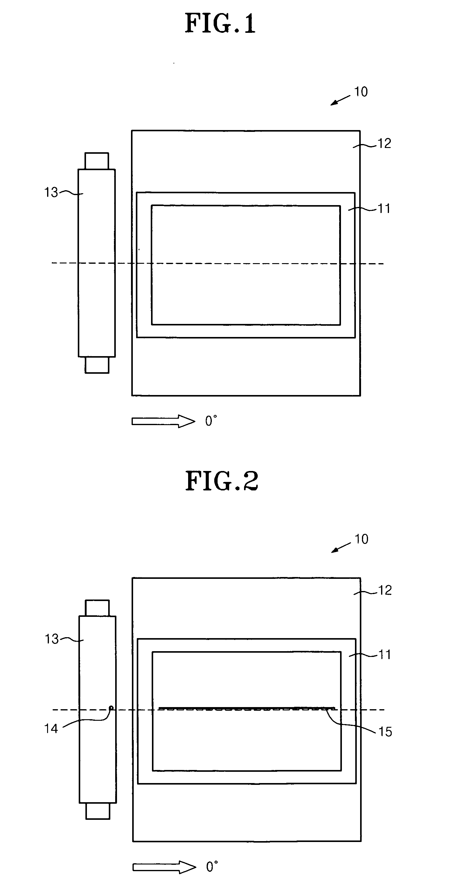
[0022] Referring to the drawing, the alignment layer rubbing apparatus 100 includes a table 120, on which a glass substrate 110 is seated, and a rubbing roller 130 positioned on top of the table 120 and adapted to move horizontally.

[0023] The table 120 and the rubbing roller 130 are initially positioned parallel to each other and are tilted at a predetermined angle relative to the horizontal direction, preferably at an angle of 1° to 15° or −1° to −15°.

[0024] If the tilt angle is less than ±1°, there is litt...


PUM

PropertyMeasurementUnit
Angleaaaaaaaaaa
Angleaaaaaaaaaa
Angleaaaaaaaaaa

Abstract

Disclosed is an alignment layer rubbing apparatus including a table for seating a glass substrate and a rubbing roller movably positioned on top of the table so as to rub an alignment layer of the glass substrate seated on the table. The table and the rubbing roller are tilted at a predetermined angle, and the rubbing roller is adapted to move at an angle of 0° on the table. Therefore, the damage inflicted on the alignment layer due to poor aligning of rubbing fabric attached to the rubbing roller or due to the existence of an alien substance on a surface of the rubbing roller is not concentrated, but rather spans across a region. This reduces the occurrence of rubbing stains and the visibility of damaged parts.

Description

BACKGROUND OF THE INVENTION [0001] 1. Field of the Invention [0002] The present invention relates to an alignment layer rubbing apparatus, and more particularly to an alignment layer rubbing apparatus capable of minimizing a rubbing defect of an alignment layer resulting from, for example, an alien substance attached to a rubbing roller during an alignment layer rubbing process for determining the initial alignment direction of liquid crystal molecules in an LCD. [0003] 2. Description of the Prior Art [0004] As generally known in the art, an LCD is an electronic device adapted to convert various types of electric information, which is created by different devices, into visual information by using the change of transmittance of liquid crystals, which depends on the applied voltage, and display corresponding images. LCDs are used as the information display window of portable terminals and laptop computers, for example. [0005] The LCD includes an upper glass substrate, a lower glass su...

Claims


Application Information

Patent Timeline
IPC IPC(8): D01F11/02B24B51/00G02F1/1337
CPCG02F1/1303G02F1/133784G02F1/1337
Inventor RYU, SUNG GUKPARK, HAE JIN
Owner BOE HYDIS TECH
Learn More