Signal processing system and signal processing program

Inactive Publication Date: 2007-06-14
OLYMPUS CORP
View PDF1 Cites 20 Cited by
  • Summary
  • Abstract
  • Description
  • Claims
  • Application Information

AI Technical Summary

Benefits of technology

[0011] According to this invention, a nearby region similar to the target region regarding which noise reduction processing is to be performed is selected, the amount of noise is estimated for each of the target region and the nearby region, and noise reduction processing is performed according to the estimated noise amount, so high-precision noise amount estimation and optimal noise reduction can be made throughout the entire image, thereby yielding high-precision signals.
[0099] According to this invention, smoothing processing of luminance signals is performed on target regions regarding which determination has been made to belong to a noise range, and correction processing of luminance signals is performed on target regions regarding which determination has been made not to belong to a noise range, so discontinuity due to luminance noise reduction processing can be prevented from occurring, and high-quality signals can be obtained.

Problems solved by technology

The fixed pattern noise is noise that originates primarily in the image pickup device, and is typified by defective pixels or the like.
On the other hand, random noise is generated in the image pickup device and analog circuit, and has characteristics close to white noise properties.

Method used


Image

  • Signal processing system and signal processing program
  • Signal processing system and signal processing program
  • Signal processing system and signal processing program

Examples


embodiment 1

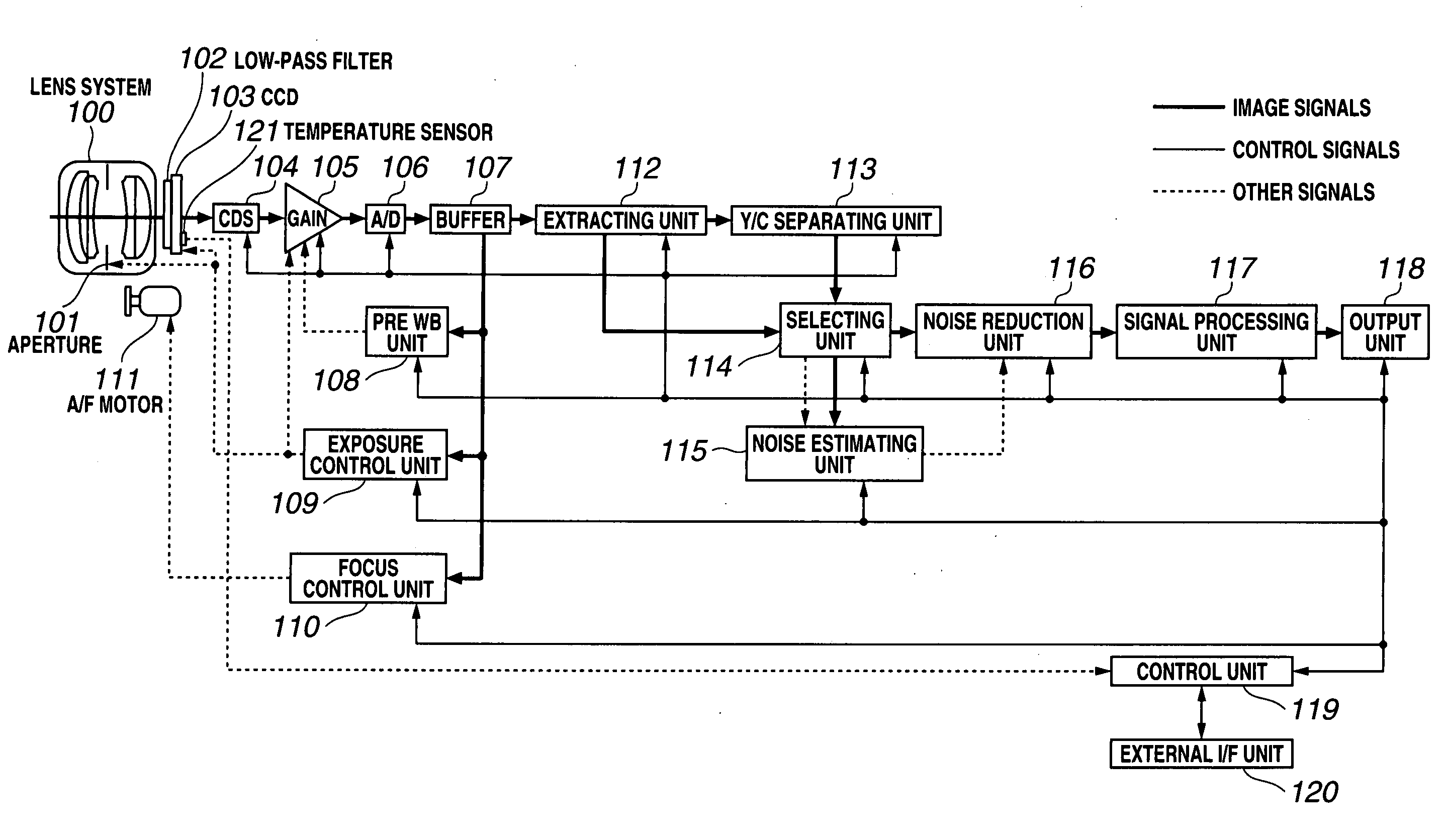
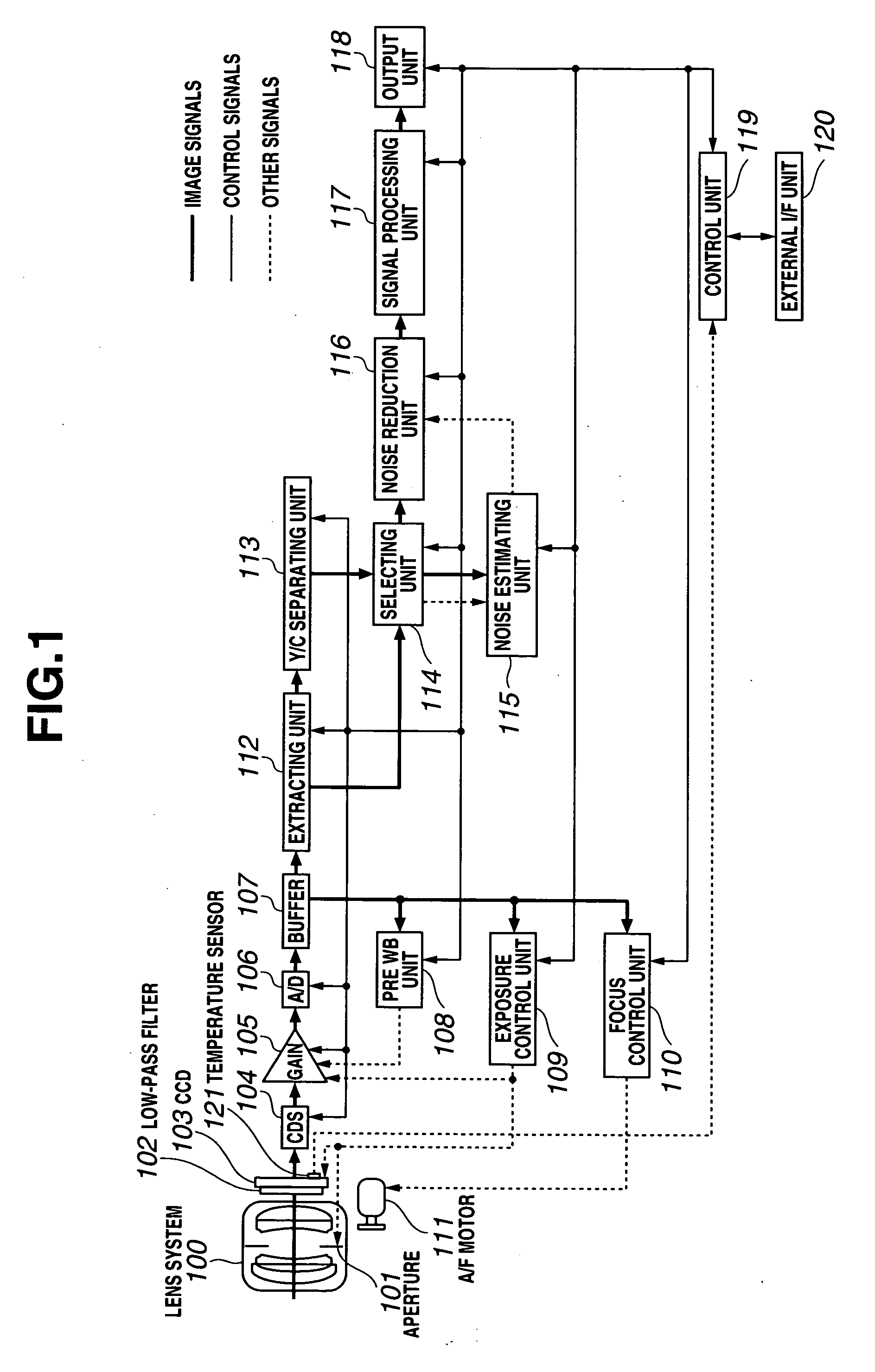
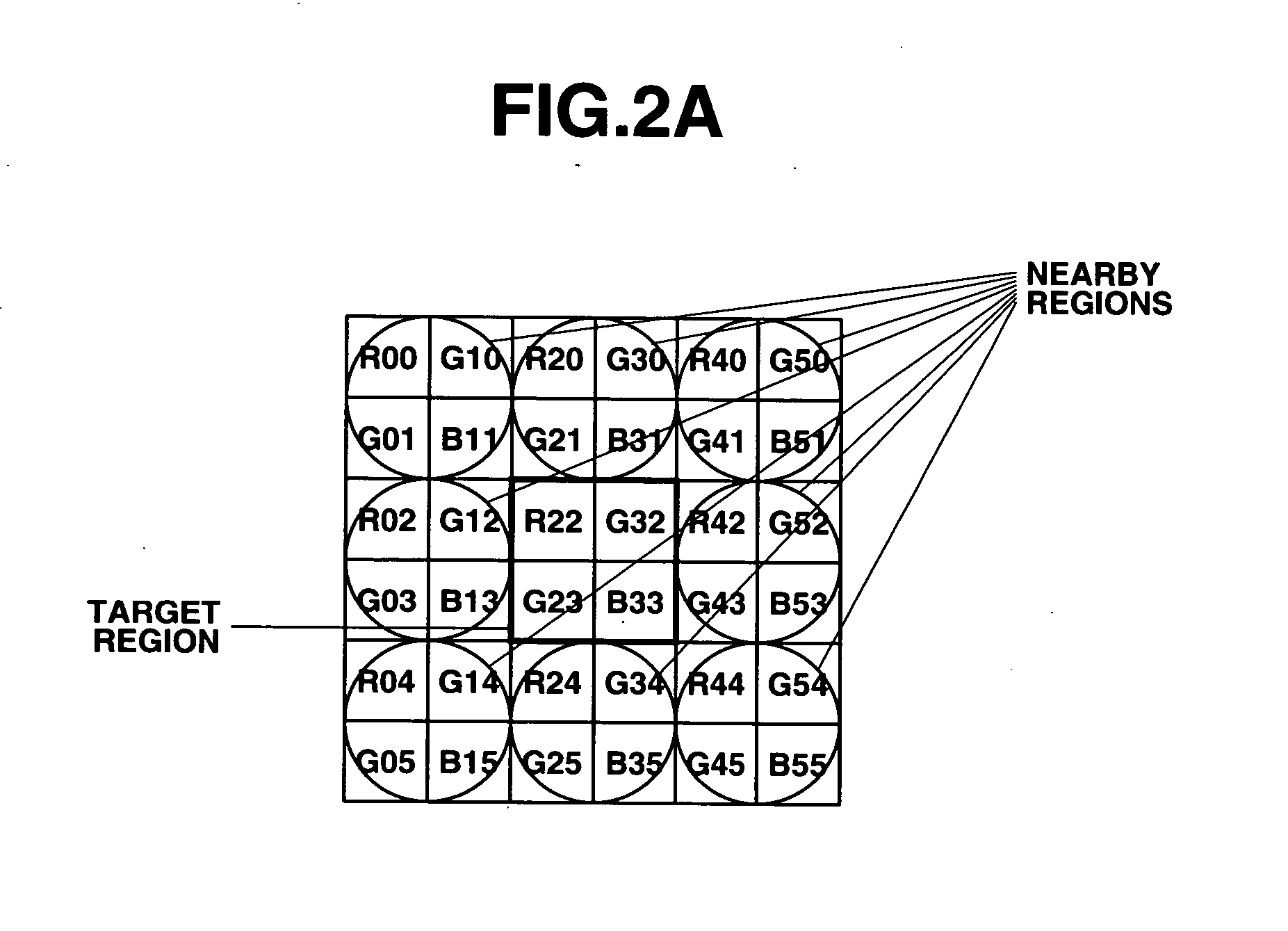
[0128]FIG. 1 is a configuration diagram of a signal processing system according to Embodiment 1 of the present invention, FIG. 2A through FIG. 2D are explanatory diagrams relating to a local region with a Bayer color filter, FIG. 3 is a configuration diagram of the selecting unit shown in FIG. 1, FIG. 4A through FIG. 4D are explanatory diagrams relating to hue classification based on spectral gradient, FIG. 5 is a configuration diagram of the noise estimating unit shown in FIG. 1, FIG. 6A through FIG. 6D are explanatory diagrams relating to noise amount estimation, FIG. 7 is a configuration diagram of the noise reduction unit shown in FIG. 1, FIG. 8 is a configuration diagram of a signal processing system according to another form of Embodiment 1, and FIG. 9 is a flow chart of noise reduction processing with Embodiment 1.

[Configuration]

[0129]FIG. 1 is a configuration diagram of Embodiment 1 of the present invention. An image captured by a lens system 100, aperture 101, low-pass fi...

embodiment 2

[0172]FIG. 10 is a configuration diagram of a signal processing system according to Embodiment 2 of the present invention, FIG. 11A through FIG. 11C are explanatory diagrams relating to a local region in a color difference line sequential color filter, FIG. 12 is a configuration diagram of the selecting unit shown in FIG. 10, FIG. 13 is a configuration diagram of the selecting unit according to another configuration, FIG. 14 is a configuration diagram of the noise estimating unit shown in FIG. 10, and FIG. 15 is a flow chart of noise reduction processing with Embodiment 2.

[Configuration]

[0173]FIG. 10 is a configuration diagram of Embodiment 2 of the present invention. The present embodiment is a configuration wherein the connection from the extracting unit 112 to the selecting unit 114 in Embodiment 1 of the present invention has been deleted. The basic configuration is equivalent to that in Embodiment 1, and the same components are assigned with the same names and numerals.

[Ope...


PUM


Abstract

A signal processing system for performing noise reduction processing on signals from an image pickup device in front of which is arranged a color filter. The system includes extracting unit for extracting a local region formed by a target region which noise reduction processing is performed and at least one or more nearby regions which exist neighborhood of the target region, Y / C separating unit for separating luminance signals and color difference signals for each of the target region and the nearby regions, selecting unit for selecting the nearby regions similar to the target region, noise estimating unit for estimating the amount of noise from the target region and the selected nearby regions, and noise reduction unit for reducing noise in the target region based on the amount of noise.

Description

CROSS REFERENCE TO RELATED APPLICATION [0001] This application is a continuation application of PCT / JP2005 / 012478 filed on Jul. 6, 2005 and claims the benefit of Japanese Application No. 2004-201091 filed in Japan on Jul. 7, 2004, the entire contents of which are incorporated herein by their reference.BACKGROUND OF THE INVENTION [0002] 1. Field of the Invention [0003] The present invention relates to processing for random noise reduction in color signals and luminance signals due to an image pickup device system, and further relates to a signal processing system and a signal processing program which reduce only noise components with high precision by dynamically estimating the amount of noise generated, without any influence of shooting conditions. [0004] 2. Description of the Related Art [0005] Noise components included in digitized signals obtained from an image pickup device and an analog circuit and an A / D converter associated with the image pickup device can be generally classi...

Claims


Application Information

Patent Timeline
IPC IPC(8): H04N5/217G06T1/00G06T3/00G06T5/00G06T5/20
CPCH04N5/357H04N9/045H04N9/646G06T5/002G06T5/20G06T2207/10024H04N25/60H04N23/84H04N25/136H04N25/134G06T5/70
Inventor TSURUOKA, TAKAO
Owner OLYMPUS CORP
Why Eureka
Try Eureka