Oscillation damping means for magnetically levitated systems

Active Publication Date: 2007-06-14
LAWRENCE LIVERMORE NAT SECURITY LLC
View PDF13 Cites 24 Cited by
  • Summary
  • Abstract
  • Description
  • Claims
  • Application Information

AI Technical Summary

Benefits of technology

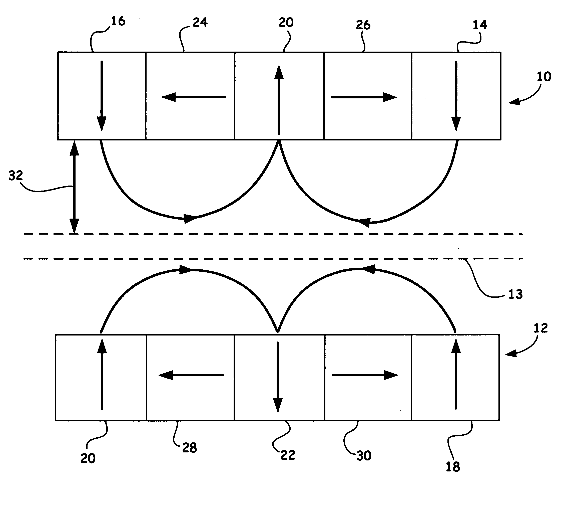
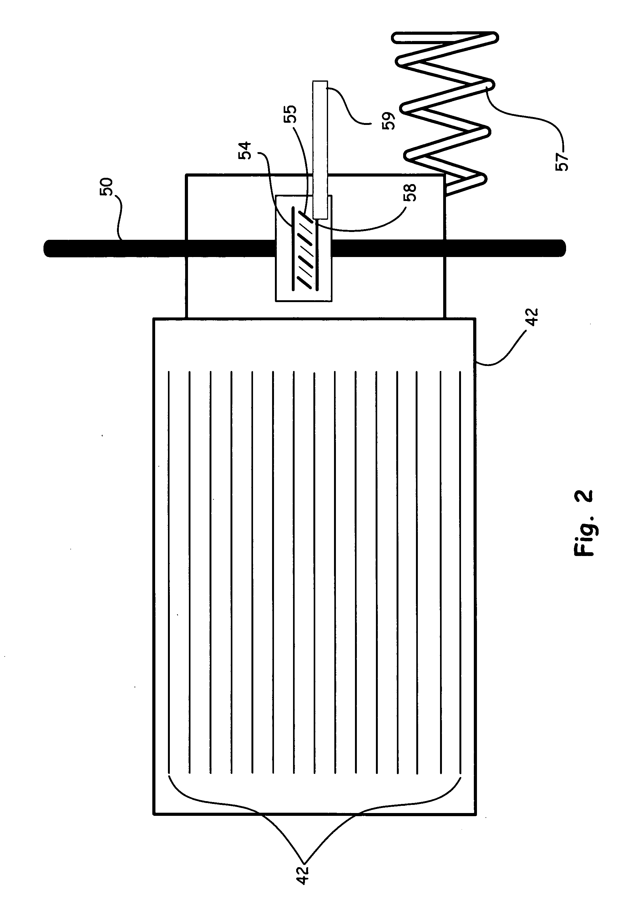
[0013] Another aspect of the present invention is directed to a method for suppressing induced oscillations of a magnet rail system, including; positioning a track circuit between one or more pair of Halbach arrays, wherein the track circuit further includes a plurality of predetermined transverse cuts to periodically separate the track circuit at desired intervals so as to produce a plurality of short tracks; coupling one or more dampers at each of the short tracks so as to suppress unwanted vertical, horizontal, and longitudinal induced oscillations in the magnet rail system, wherein each damper can include: a support shaft; a fixed friction disc coupled to the support shaft; and a movable friction disc coupled to the support shaft and additionally coupled to an inner edge of the short track.

Problems solved by technology

However, such maglev systems as disclosed in the incorporated applications often produce deleterious resonant frequency oscillations of at least about 1 Hz in all principal modes of motion when in operation.
These oscillations can be stimulated by imperfections in the “track,” by the drive system, or by inherent instability arising from some special characteristic of the levitation system itself.
Typically the levitation system is not capable, of itself, to damp out these oscillations and other means is therefore required.
While in some cases damping can be effected in the moving frame (i.e., in the frame of the moving object), this type of damping is not only characteristically less effective, but also may be the driving source for instabilities of the “dissipative” type, a type encountered in other contexts, such as in bearing-supported rotating systems.

Method used


Image

  • Oscillation damping means for magnetically levitated systems
  • Oscillation damping means for magnetically levitated systems
  • Oscillation damping means for magnetically levitated systems

Examples


Embodiment Construction

[0021] Referring now to the following detailed information, and to incorporated materials; a detailed description of the invention, including specific embodiments, is presented.

[0022] Unless otherwise indicated, numbers expressing quantities of ingredients, constituents, reaction conditions and so forth used in the specification and claims are to be understood as being modified by the term “about.” Accordingly, unless indicated to the contrary, the numerical parameters set forth in the specification and attached claims are approximations that may vary depending upon the desired properties sought to be obtained by the subject matter presented herein. At the very least, and not as an attempt to limit the application of the doctrine of equivalents to the scope of the claims, each numerical parameter should at least be construed in light of the number of reported significant digits and by applying ordinary rounding techniques. Notwithstanding that the numerical ranges and parameters se...


PUM


Abstract

The present invention presents a novel system and method of damping rolling, pitching, or yawing motions, or longitudinal oscillations superposed on their normal forward or backward velocity of a moving levitated system.

Description

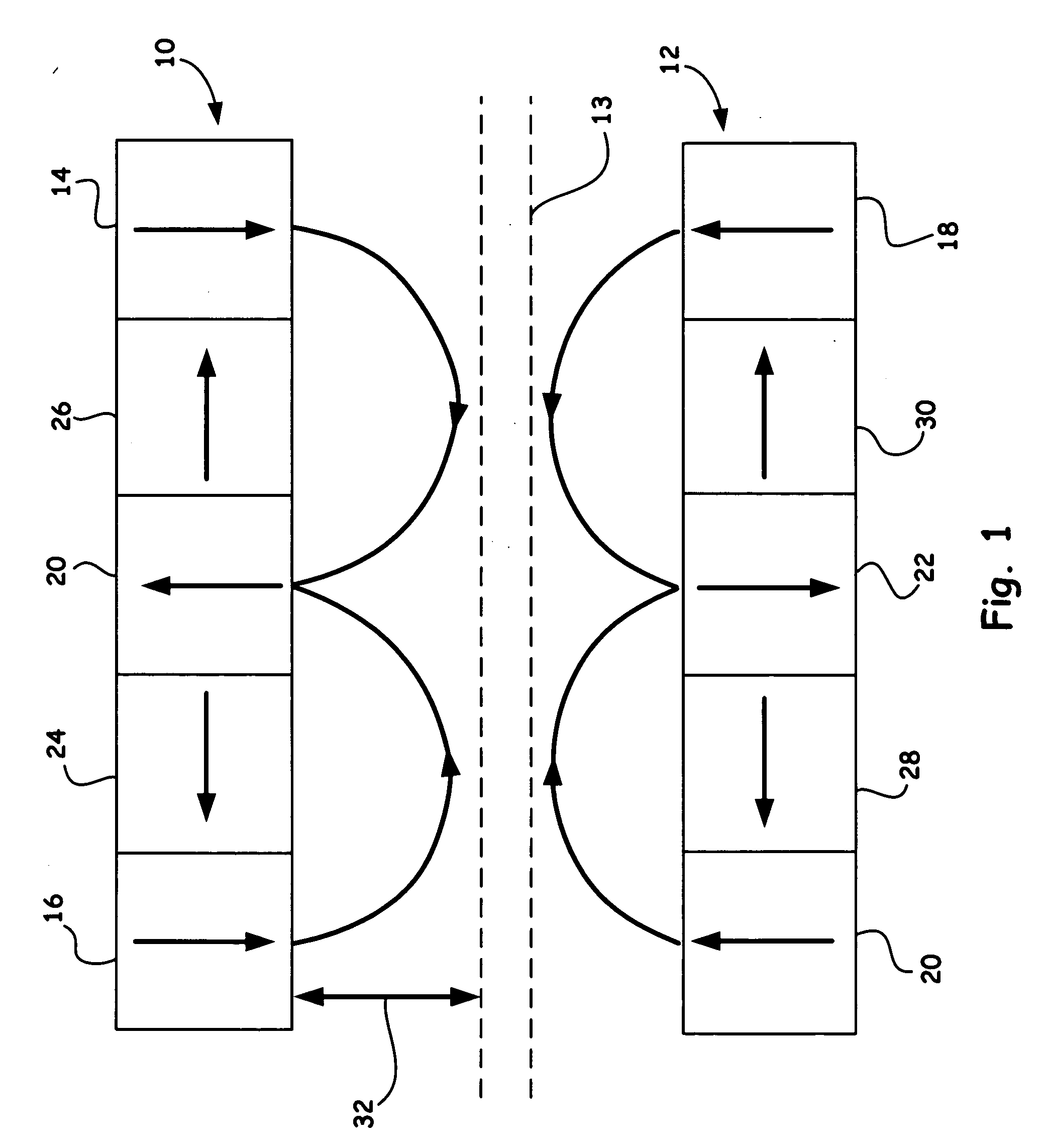
RELATED APPLICATION [0001] This application claims priority from U.S. Provisional Patent Application No. 60 / 749,157, entitled “OSCILLATION DAMPING MEANS FOR MAGNETICALLY LEVITATED SYSTEMS,” filed on Dec. 9, 2005, and is incorporated by reference in its entirety.[0002] The United States Government has rights in this invention pursuant to Contract No. W-7405-ENG-48 between the United States Department of Energy and the University of California for the operation of Lawrence Livermore National Laboratory.BACKGROUND OF THE INVENTION [0003] 1. Field of the Invention [0004] The present invention relates generally to magnetic levitation systems for moving objects, and more specifically, to a means for damping deleterious oscillations involving magnetic levitation train systems. [0005] 2. Description of Related Art [0006] Halbach arrays, invented by Klaus Halbach in the 1980s for use in particle accelerators, represent a maximally efficient way to arrange permanent-magnet material when it is...

Claims


Application Information

Patent Timeline
IPC IPC(8): B60L13/06
CPCB60L13/04B60L2200/26B60L13/06
Inventor POST, RICHARD F.
Owner LAWRENCE LIVERMORE NAT SECURITY LLC
Why Eureka
Try Eureka