
Apparatus, method and computer program product for reading information stored in storage medium, and storage medium for storing information based on charge amount

a technology of information storage and storage media, applied in the direction of digital storage, coding, instruments, etc., can solve the problems of large reduction of the output voltage affecting the operation of the memory element, and affecting the operation of the storage medium

Active Publication Date: 2007-06-07
KIOXIA CORP
View PDF14 Cites 62 Cited by
  • Summary
  • Abstract
  • Description
  • Claims
  • Application Information

AI Technical Summary

Benefits of technology

[0011] According to still another aspect of the present invention, a reproducing method includes reading each 2-bit code by a charge amount which is held by each of a plurality of memory elements included in a storage unit and capable of holding an electric charge, using three threshold values having a fixed minimum value or a fixed maximum value corresponding to each of the memory elements indicating the 2-bit codes related to each other so that the Hamming distance between adjacent codes is unity in four ranges determined by the charge amount with respect to the three threshold values; detecting whether a first bit string consisting of right bits of the 2 bit codes read or a second bit string consisting of left bits of the 2 bit codes read has an error; and upon detection of the error, changing a threshold value corresponding to the bit string having the error other than a fixed threshold value to secure a correct bit string.

Problems solved by technology

Since the accumulated charge amount is reduced by natural discharge also even when a read or write operation is not performed for a long time the situation in which the information cannot be read is liable to occur after power is not switched on for a long time especially with regard to a nonvolatile memory.
In the multi-valued memory, on the other hand, the decreased output of the memory element by discharge has so great an effect that the number of read operations is limited.
The method described in U.S. Pat. No. 5,909,449, however, poses a problem that when a long time has passed from a write operation and the output voltage of the memory element has greatly decreased, the information to be written by the refresh operation cannot be read from the memory elements.
Therefore, the memory elements that have passed a long time from the write operation cannot be refreshed, with the result that the information cannot be read correctly.

Method used


Image

  • Apparatus, method and computer program product for reading information stored in storage medium, and storage medium for storing information based on charge amount
  • Apparatus, method and computer program product for reading information stored in storage medium, and storage medium for storing information based on charge amount
  • Apparatus, method and computer program product for reading information stored in storage medium, and storage medium for storing information based on charge amount

Examples


first embodiment

[0023] A reproducing apparatus detects an error of the read-out 2-bit information for each bit, changes a threshold value for determining a code stored in a memory element on detection of an error, and then reads the information again.

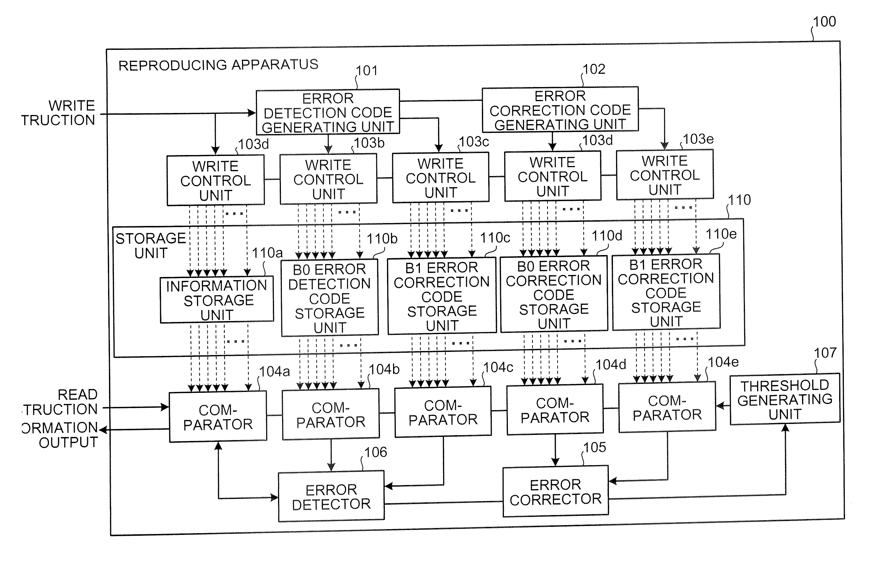
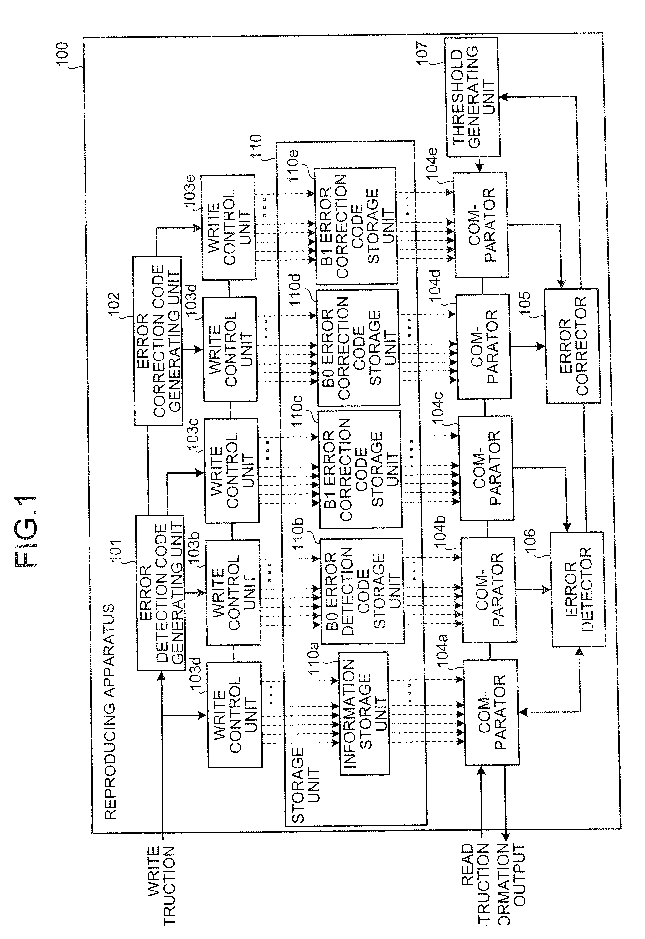
[0024]FIG. 1 is a block diagram showing a configuration of a reproducing apparatus 100 according to the first embodiment. As shown in FIG. 1, the reproducing apparatus 100 includes a storage unit 110, an error detection code generating unit 101, an error correction code generating unit 102, write control units 103a to 103e, comparators 104a to 104e, an error corrector 105, an error detector 106, and a threshold generating unit 107.

[0025] The storage unit 110 is a memory element for storing information in accordance with the magnitude relation between the charge amount and a predetermined charge amount threshold value, and is, for example, a generally-used semiconductor memory such as a flash memory or a DRAM (dynamic random access memory). The storag...

second embodiment

[0092] In a reproducing apparatus the charge is accumulated in the memory element in such a manner that the time before an error occurs at the time of read operation with the value of the charge amount exceeding the minimum or maximum threshold value due to discharge is longer than the time before an error occurs by exceeding the other threshold values, and upon detection of an error at the time of read operation, the minimum or maximum threshold value, as the case may be, is fixed while a new threshold value is generated thereby to read the information again.

[0093] The configuration of the reproducing apparatus according to the second embodiment is similar to that of the reproducing apparatus according to the first embodiment shown in the block diagram of FIG. 1, and therefore not explained again. The second embodiment is different from the first embodiment in the configuration of the memory elements constituting the storage unit 110.

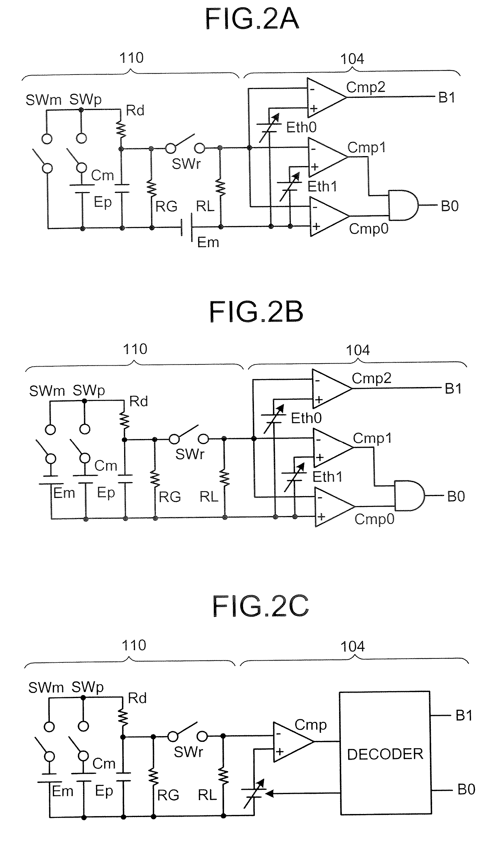
[0094]FIG. 7 is a diagram illustrating an equi...


PUM


Abstract

A reproducing apparatus includes a storage unit including a plurality of memory elements each capable of holding an electric charge, each memory element indicating a 2-bit code which is related to each other so that the Hamming distance between adjacent codes is unity in four ranges determined by a charge amount with respect to three threshold values with the minimum or maximum value thereof as a fixed value; a reading unit that reads each 2-bit code by the charge amount which is held in each memory element using the three threshold values corresponding to each memory element; an error detector that detects whether a first bit string consisting of right bits of the 2 bit codes read or a second bit string consisting of left bits of the 2 bit codes read has an error; and a threshold changing unit that, upon detection of the error, changes a threshold value corresponding to the bit string having the error other than a fixed threshold value to secure a correct bit string.

Description

CROSS-REFERENCE TO RELATED APPLICATIONS [0001] This application is based upon and claims the benefit of priority from the prior Japanese Patent Application No. 2005-350819, filed on Dec. 5, 2005; the entire contents of which are incorporated herein by reference. BACKGROUND OF THE INVENTION [0002] 1. Field of the Invention [0003] This invention relates to an apparatus, a method, and a computer program product for reading information stored in a storage medium, and a storage medium where information is stored in accordance with charge amount. [0004] 2. Description of the Related Art [0005] In recent years, a semiconductor memory element such as a flash memory for storing information in accordance with the charge amount held therein are widely known. Also, a multi-valued memory technique for storing the information of 2 bits or more by setting a plurality of threshold values of the charge amount has been developed. [0006] The memory element of charge accumulation type is discharged wit...

Claims


Application Information

Patent Timeline
IPC IPC(8): G11C29/00G06F11/00
CPCG06F11/1072G11C11/56
Inventor KANNO, SHINICHI
Owner KIOXIA CORP
Learn More