
Communication system and communication method

Inactive Publication Date: 2007-06-07
NEC CORP
View PDF2 Cites 51 Cited by
  • Summary
  • Abstract
  • Description
  • Claims
  • Application Information

AI Technical Summary

Benefits of technology

[0022] An object of the present invention, which takes the above-described problems of conventional techniques into consideration, is to provide a communication system realizing high reliability which enables, in a network having various topology in which a plurality of communication paths exist between base nodes communicating and a plurality of relay nodes exist on each communication path, occurrence of congestion to be suppressed in normal operation and enables communication to be continued even when a failure occurs.
[0024] A further object of the present invention is to provide a communication system whose setting is simple.
[0025] A still further object of the present invention is to provide a failure detection means having small load on a device.

Problems solved by technology

The above-described conventional methods, however, have the problems set forth in the following.
First is that the technique using link aggregation is only applicable to two nodes adjacent to each other and is not applicable to a network having various topology.
Even a link between adjacent nodes is given high reliability, however, just a fault such as a failure occurring in any one of the relay nodes on the communication path disables two nodes communicating with each other to communicate.
In addition, because link aggregation is applicable only between two nodes adjacent to each other, it is not applicable to a network in which two nodes communicating with each other are connected by a plurality of communication paths including at least one relay node.
Next, another problem is that, when using a routing protocol such as OSPF or BGP, detecting a failure on a communication path takes time, so that continuation of communication is disabled until detection of a failure.
Even when a failure is detected, a further problem occurs that because newly obtaining a communication path having no failure takes time, switching a communication path developing a fault to a communication path having no failure interrupts communication until communication is resumed.
Furthermore, since setting a routing protocol requires detailed and advanced knowledge about the routing protocol, setting is so difficult for a common user that a possibility of erroneous setting is increased to prevent efficient operation of a network.
Next, the technique of detecting a failure on a communication path by transmission and reception, by nodes communicating with each other, of a monitoring packet (e.g. PING packet) which designates a partner node as a destination, which is a failure detection technique used in combination with the NAT technique, has a problem that because as the number of partner nodes is increased, the number of monitoring packets to be transmitted is increased, load on processing for detecting a failure is extremely increased.
Further problem is that since a destination address of each of all the partner nodes should be set, the number of items to be set is increased as the number of partner nodes is increased, so that a possibility of erroneous setting by a manager of a network is increased.

Method used


Image

  • Communication system and communication method
  • Communication system and communication method
  • Communication system and communication method

Examples


first embodiment

[0064] First embodiment of the present invention will be described in detail with reference to the drawings.

Structure of Communication System

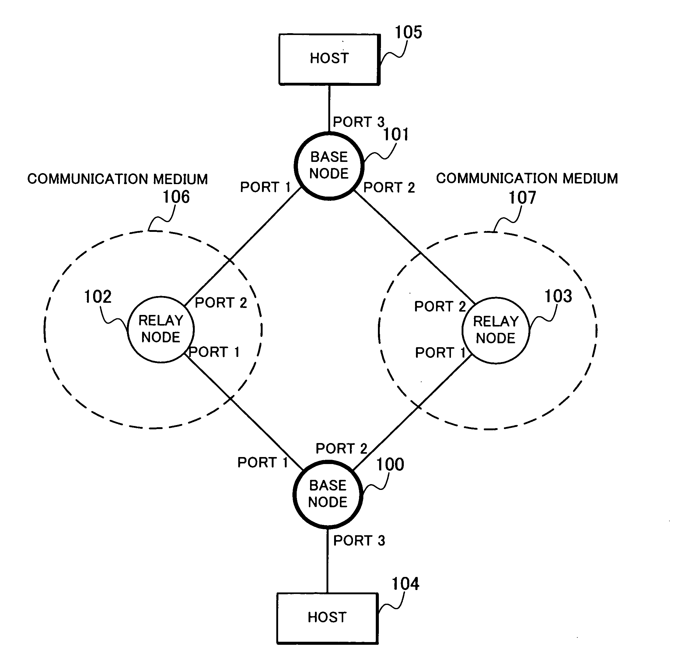
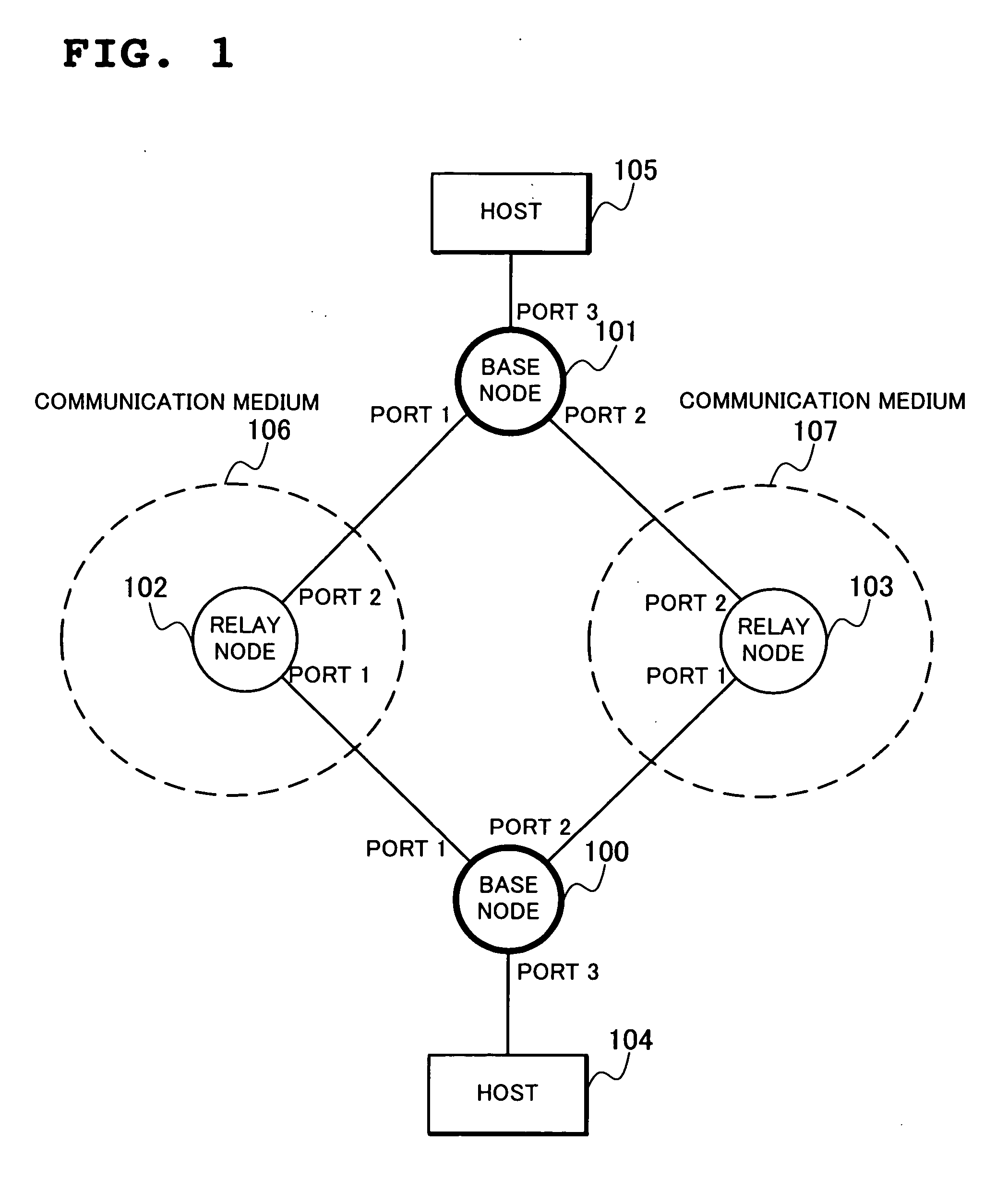
[0065]FIG. 1 shows a structure of a communication system according to the first embodiment of the present invention.

[0066] The communication system shown in FIG. 1 includes two base node 100 and base node 101, a communication medium 106 formed of a relay node 102, a communication medium 107 formed of a relay node 103, and two host 104 and host 105.

[0067] Here, the relay node, which is a node forming the communication medium, relays a data frame transmitted from the base node to transfer the same to a predetermined destination.

[0068] Base node, which is a node connected to the communication medium and has an arbitrary number of hosts accommodated in a port not connected to the communication medium among ports belonging to the base node directly or through at least one node, transfers a data frame transmitted from the host and the communica...

second embodiment

[0251] Second embodiment of the present invention will be described in detail with reference to the drawings.

[0252] The second embodiment will be described with respect to a method of providing a highly reliable communication system by using a port mapping table.

(Structure of Communication System)

[0253] Since a structure of a communication system according to the second embodiment is the same as that of the communication system according to the first embodiment shown in FIG. 1, description thereof will be omitted.

(Structure of Base Node)

[0254]FIG. 7 is a block diagram showing a structure of the base nodes 100 and 101 according to the second embodiment.

[0255] The structure of the base node 100 (also the case with the base node 101) in the second embodiment differs from that of the first embodiment in that the base node 100 includes a port mapping table 701 and a port conversion unit 702.

[0256] By assigning, to a virtual port set in the virtual port setting table 312, a port ...

third embodiment

[0307] Third embodiment of the present invention will be described in detail with reference to the drawings.

[0308] Third embodiment will be described with respect to a method of realizing high reliability in such a communication system as has a communication medium connected to three or more base nodes.

(Structure of Communication System)

[0309]FIG. 10 shows a structure of a communication system according to the third embodiment.

[0310] The structure of the communication system according to the third embodiment differs from the first and second embodiments in that three base nodes 100, 101 and 1000 are connected to two communication medium 106 and communication medium 107. The base node 1000 is connected to the relay node 102 by the port 1, to the relay node 103 by the port 2 and to a host 1001 by the port 1(*3?).

[0311] While the communication system shown in FIG. 10 has the three, the base node 100, the base node 101 and the base node 1000 connected to the communication media 10...


PUM


Abstract

A base node (100) and a base node (101) transmit a keep alive frame broadcast by a relay node forming a communication medium (106) and a communication medium (107) from a port 1 and a port 2, monitor an arrival state of the keep alive frame at each port, and in normal operation, assume the two communication media connected to the port 1 and the port 2 as one node to expand a communication band and at failure detection, continue communication by using only a communication medium connected to a port at which no failure is detected.

Description

FIELD OF THE INVENTION [0001] The present invention relates to a communication system realizing high reliability and, more particularly, a communication system having high reliability which enables congestion to be suppressed by transmitting data frames by using a plurality of communication paths to expand a communication band in normal operation when no failure is detected and enables communication to be continued by using only a communication path with no failure detected when a failure is detected. DESCRIPTION OF THE RELATED ART [0002] In recent years, computer networks have been introduced in every field in society to play an important social role not only as a communication means such as mutual understanding by electronic mail and information disclosure by a Web site but also as infrastructure for providing various kinds of services. [0003] Today, when computer networks are indispensable for society, deep effects will be exercised on users by a situation that disables sufficien...

Claims


Application Information

Patent Timeline
IPC IPC(8): H04J1/16H04Q7/00H04L12/56H04W40/22H04W40/24
CPCH04W40/22H04W40/24
Inventor OGASAHARA, DAISAKUUMAYABASHI, MASAKIENOMOTO, NOBUYUKIHIDAKA, YOUICHIIWATA, ATSUSHIARUTAKI, AKIRA
Owner NEC CORP
Learn More