Beam optical component for charged particle beams

a beam and optical component technology, applied in the direction of beam deviation/focusing by electric/magnetic means, instruments, magnetic discharge control, etc., can solve the problems of reducing the focussing quality of the beam optical component, affecting the accuracy of beam optical components, and affecting the alignment quality of two or more electrodes or pole shoes, etc., to achieve easy disassembly, improve focussing quality, and eliminate distorting or tilting forces

Active Publication Date: 2007-06-07
ICT INTEGRATED CIRCUIT TESTING GESELLSCHAFT FUER HALBLEITERPRUEFTECHNIK GMBH
View PDF7 Cites 14 Cited by
  • Summary
  • Abstract
  • Description
  • Claims
  • Application Information

AI Technical Summary

Benefits of technology

[0013] In particular, it is an aspect of the present invention to provide a beam optical component which ensures a high precision for the alignment of the first electrode or pole piece with respect to the other electrodes or pole pieces of the beam optical component.
[0032] Preferably, at least one of the distance pieces is a spherically shaped, since spherically shaped bodies can be manufactured to a high geometrical precision and since a sphere defines the same distance between two electrodes independent of the orientation of the spherically shaped body. Further, a spherically shaped body as a distance piece not only provides for a minimum distance between two adjacent electrodes, but also provides for a lateral fixation of two adjacent electrodes with respect to each other if the spherically shaped bodies are partially sunk into the appropriate recess within the respective electrodes.

Problems solved by technology

To achieve this precision usually represents a major challenge.
However, when tightening the screws during re-assemblage of the beam optical component to clamp the electrodes together, the electrodes often become distorted or tilted with respect to each other, which diminishes the focussing quality of the beam optical component.
Similar alignment problems of two or more electrodes or pole shoes also occur when two or more electrodes or pole shoes of an electrostatic or magnetic mirror or a spectrometer have to be assembled.

Method used


Image

  • Beam optical component for charged particle beams
  • Beam optical component for charged particle beams
  • Beam optical component for charged particle beams

Examples


Embodiment Construction

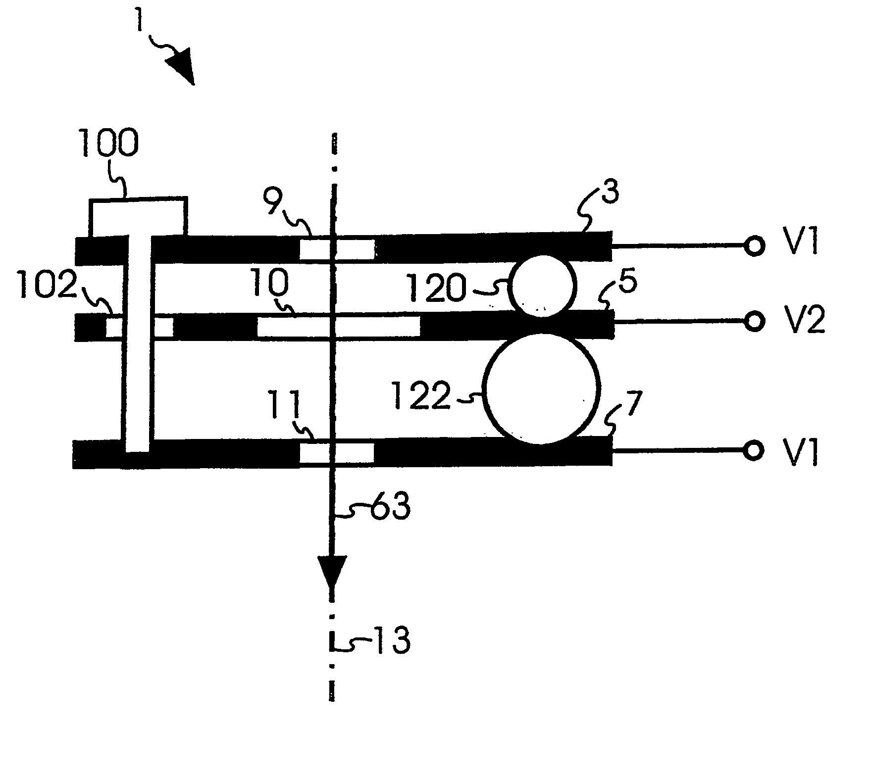
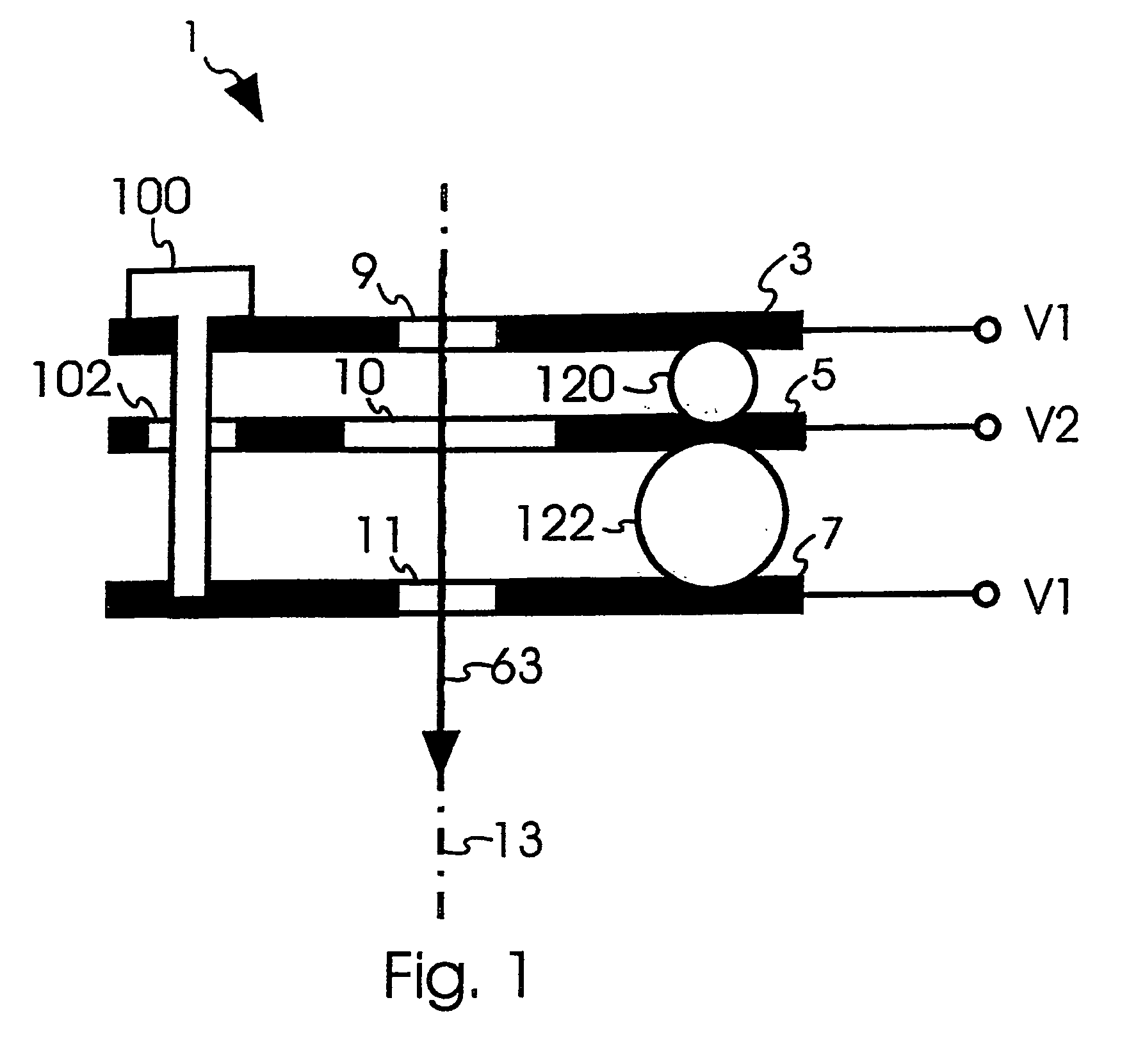
[0047] The term “beam optical component” in claim 1 preferably refers to electrostatic or magnetic lenses, electrostatic or magnetic mirrors, electrostatic or magnetic deflectors, electrostatic or magnetic and other components that act on a charged particle beam by means of electrostatic and / or magnetic fields. Beam optical components according to the invention may be used in charged particle beam devices like a charged particle beam microscope to probe a specimen, e.g. a scanning electron microscope (SEM), a transmission electron microscope (TEM), a scanning transmission microscope (STEM), or a device that uses the charged particle beams to structure a specimen like, e.g. an electron beam pattern generators used to structure a lithographic mask, or a focused ion beam device (FIB) to slice or mill a specimen.

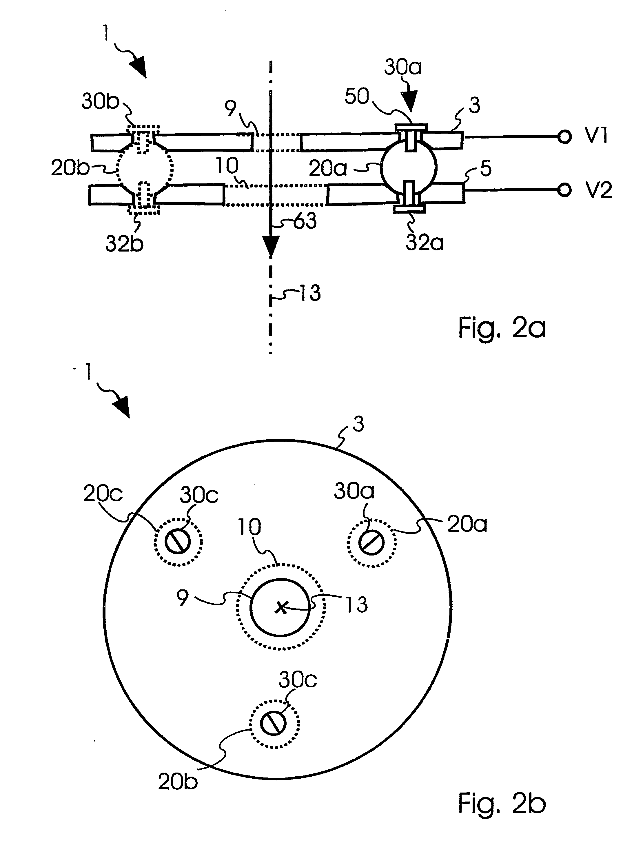
[0048]FIG. 2a depicts schematically a cross section through the center of a first beam optical component 1 according to the invention. In this embodiment, the beam optical comp...


PUM


Abstract

The present invention relates to a beam optical component (1, 201) for acting on a charged particle beam (63) including a first element (3; 203) having a first opening (9; 209) for acting on the charged particle beam (63), at least a second element (5; 205) for acting on the charged particle beam (63); at least one distance piece (20a, 20b, 20c) positioned between the first element (3; 203) and the second element (5; 205) to define a minimum distance between the first element (3; 203) and the second element (5; 205); and a first holding piece (30a; 30b; 30c) for abutting the first element (3) to the at least one distance piece (20a, 20b, 20c), whereby the first holding piece (30a; 30b; 30c) is attached to the at least one distance piece (20a, 20b, 20c). First and second elements (3; 203; 5; 205) are preferably electrodes or pole pieces to act on the charged particle beam by an electrostatic or magnetic force. With the first holding piece (30a; 30b; 30c) attached to the at least one distance piece, distorting mechanical forces on the first and second elements (3, 5) are reduced which improves the performance of the respective beam optical components (1; 201).

Description

FIELD OF THE INVENTION [0001] The invention relates to beam optical components for acting on charged particle beams. In particular, the present invention relates to high precision electrostatic or magnetic lenses, mirrors or spectrometers for charged particle beam devices. BACKGROUND OF THE INVENTION [0002] Improvements of charged particle beam devices, like electron microscopes or focused ion beam devices (FIB), often depend on improvements of their beam optical components. Beam optical components are, for example, electrostatic or magnetic lenses, deflectors, electrostatic or magnetic mirrors, spectrometers and the like. [0003] Beam optical components that rely on an electrostatic interaction with the charged particle beam are usually composed of two or more electrodes with openings or some other structure thereon. By applying appropriate voltages to the respective electrodes, the geometric shape of the electrodes and the electric potentials generate an electrostatic field that ca...

Claims


Application Information

Patent Timeline
Patent Type & Authority Applications(United States)
IPC IPC(8): H01J3/14H01J9/18H01J37/02H01J37/10
CPCH01J9/18H01J37/02H01J37/10H01J2237/036
Inventor FROSIEN, JUERGEN
Owner ICT INTEGRATED CIRCUIT TESTING GESELLSCHAFT FUER HALBLEITERPRUEFTECHNIK GMBH
Why Eureka
Try Eureka