Optical fuse and component for fabricating optical fuse

Inactive Publication Date: 2007-05-31
NAT INST FOR MATERIALS SCI
View PDF9 Cites 2 Cited by
  • Summary
  • Abstract
  • Description
  • Claims
  • Application Information

AI Technical Summary

Benefits of technology

[0019] The optical fuse of the present invention is designed to separate the medium as a portion playing a role in an optical coupling, from the light-absorbing body as a portion in which an irreversible change is to be induced (for inducing an irreversible change in the medium), or an irreversibly changeable portion. This provides an effect of being able to suppress an increase in insertion loss in a normal state. In addition, the optical fuse of the present invention has an effect of being able to eliminate an optical coupling in a state after an irreversible change is induced. The optical fuse-fabricating device has an effect of being able to allow such an optical fuse to be fabricated in a simple and easy way.

Problems solved by technology

This structure has a disadvantage about inherently large insertion loss due to relatively high light-absorbance capacity of the irreversibly-changeable material.
Thus, this structure also has a disadvantage about inherently large insertion loss.
Another disadvantage of the conventional optical fuse is that a light output cannot be completely cut off because a light input port is optically coupled to a light output port even after the irreversible change is induced.
An amount of deformation or light leakage of the optical waveguide in this technique is sufficient to increase a desired insertion loss but not to eliminate an optical coupling.
Thus, this technique also has a disadvantage about difficulty in completely cutting off a light output.
As above, the conventional optical fuses have problems about relatively large insertion loss in a normal state, and undesirable continuation of an optical coupling in a state after an irreversible change is induced.

Method used


Image

  • Optical fuse and component for fabricating optical fuse
  • Optical fuse and component for fabricating optical fuse
  • Optical fuse and component for fabricating optical fuse

Examples


example 1

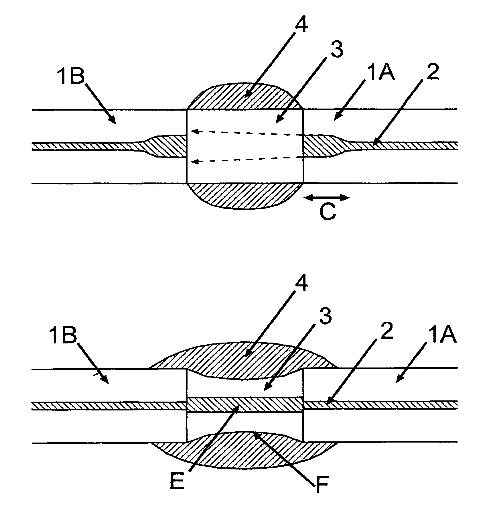
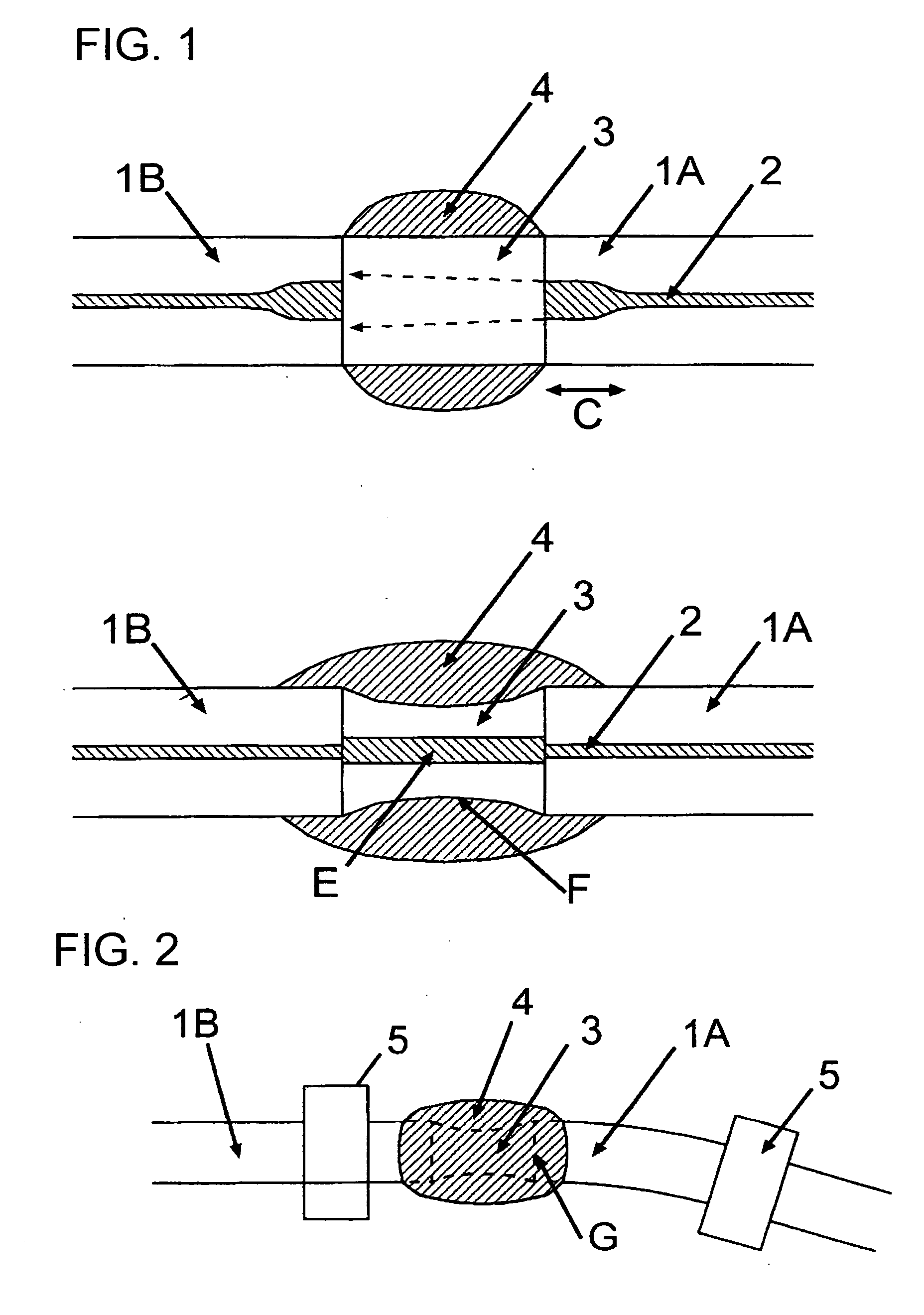
[0048] A light-emitting end of one optical fiber and a light-incident end of another optical fiber were arranged in opposed relation to one another, and a small amount of TeO2 molten liquid was inserted between the two ends. The inserted molten liquid was formed to allow an intermediate portion thereof to be constricted, and then cooled. This shape was formed by scraping a part of the liquid droplet using the two optical fibers. This technique is disclosed in Japanese Patent Laid-Open Publication No. 2003-57482 (Method and Apparatus for fabricating Glass Composite Material). When light was entered from one of the optical fibers, a light output was observed from the other optical fiber. Thus, it could be verified that an optical coupling was established through a medium composed of the transparent TeO2 glass interposed between the optical fibers. Then, a commercially available black water color was applied onto an outer peripheral surface of the TeO2 glass medium to cover over the ou...


PUM


Abstract

Disclosed are an optical fuse and a device for fabricating such an optical fuse. The optical fuse comprises a medium constituting a structure in which a light-emitting end of a first optical waveguide is coupled to a light-incident end of a second optical waveguide across the medium, and a light-absorbing body adapted to absorb the light. The medium is transparent to light passing through the structure, and the light-absorbing body is disposed in contact with an outer peripheral surface of the medium in such a manner as to allow a part of light emitted from the light-emitting end into the medium to reach the light-absorbing body. The optical-fuse fabricating device comprises a pair of first and second support members formed, respectively, with first and second through-holes for supporting an optical fiber, and a beam member mechanically connecting the first and second support member together. When the first and second support members are arranged such that respective axes of the first and second through-holes are aligned in a straight line to allow a single common optical fiber to be inserted into both the first and second through-holes, a spacial gap is formed between the single common optical fiber and the beam. The present invention can provide an optical fuse having a low insertion loss and allowing an optical coupling to be eliminated in response to an irreversible change induced therein, and a device capable of allowing such an optical fuse to be fabricated in a simple and easy way.

Description

TECHNICAL FIELD [0001] The present invention relates to an optical fuse which is one component of an optical circuit, and a device for fabricating such an optical fuse. BACKGROUND ART [0002] In connection with popularization of high-power light sources, there is a growing need for a protective device capable of protecting an optical system from an excessive light input. An optical fuse is one type of such protective devices. The optical fuse has a function of cutting off an optical line or restricting an amount of light passing therethrough in response to an excessive input, in a manner similar to a fuse incorporated in most electric products. [0003] Previously proposed optical fuses have been designed such that a medium for causing a light loss is inserted into an optical line, wherein the medium includes a material in which an irreversible change is to be induced in response to excessive light entered therein (see, for example, the following Patent Publications 1 to 3). In this st...

Claims


Application Information

Patent Timeline
IPC IPC(8): G02B6/26G02B6/42G02B6/30
CPCG02B6/2555G02B6/264G02B6/266
Inventor TODOROKI, SHINICHI
Owner NAT INST FOR MATERIALS SCI
Why Eureka
Try Eureka