
Suspension control method and device

A technology of suspension control and suspension force, which is applied in transportation and packaging, electric traction, electric vehicles, etc., can solve the problems of high control performance, no mutual influence of comprehensively collected data, hidden dangers of stable suspension of trains, etc., and achieve the effect of eliminating coupling phenomenon

Inactive Publication Date: 2013-07-10
ZHUZHOU ELECTRIC LOCOMOTIVE CO
View PDF7 Cites 14 Cited by
  • Summary
  • Abstract
  • Description
  • Claims
  • Application Information

AI Technical Summary

Problems solved by technology

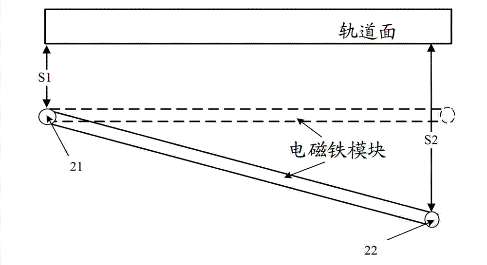
[0003] In the prior art, the two suspension control points are separately processed and calculated by two different signal processors. However, no matter how the calculation method is changed, only reference is made when calculating the control signal of one of the control points. The collected data of this control point does not integrate the collected data of another control point and the possible interaction between the two control points, so this coupling phenomenon cannot be fundamentally solved, so it is difficult to obtain high control performance , which poses a hidden danger to the stable suspension of the train

Method used


Image

  • Suspension control method and device
  • Suspension control method and device
  • Suspension control method and device

Examples


Embodiment 1

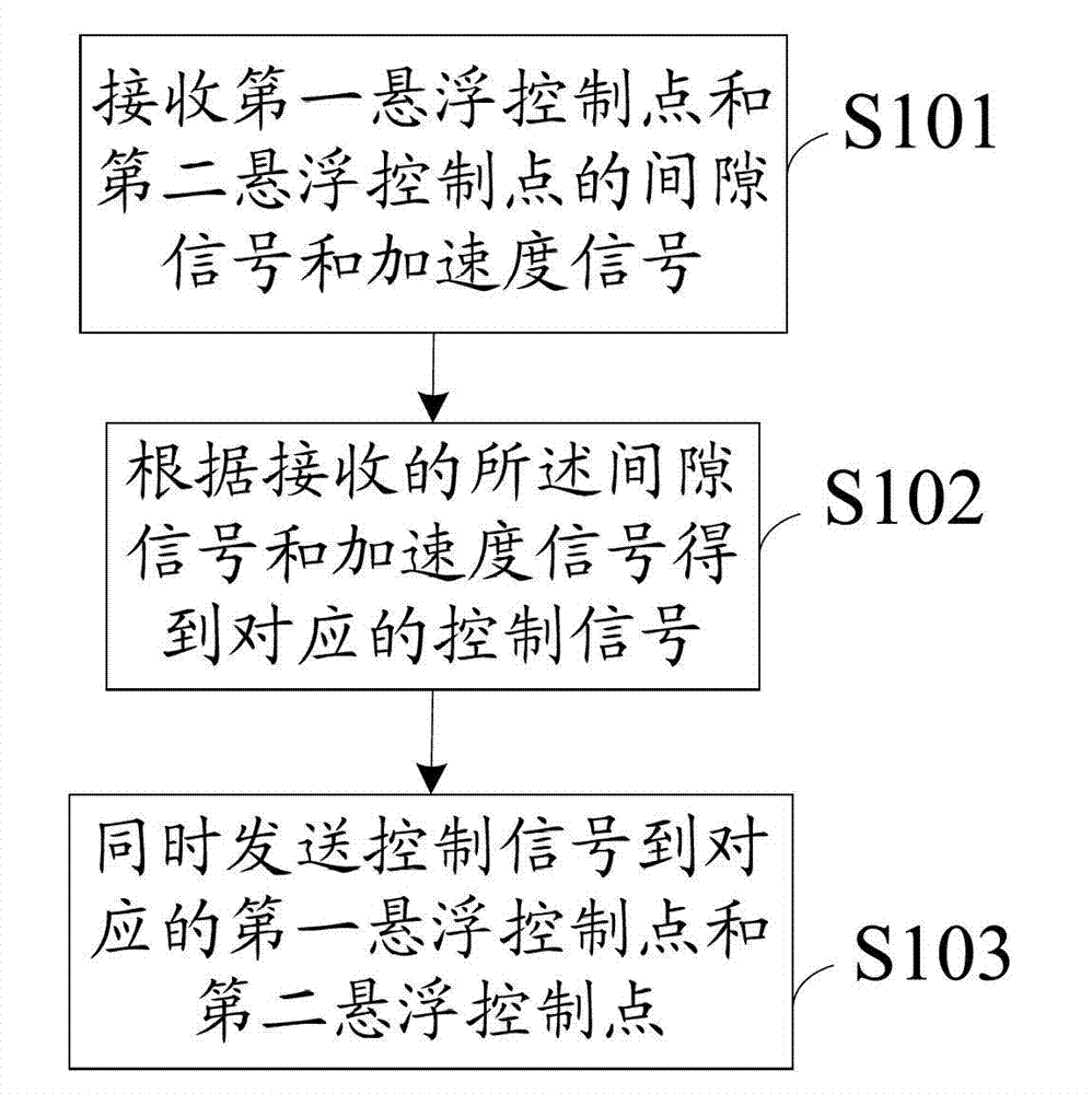
[0043] see figure 1 , which is a method flowchart of a suspension control method of the present invention, the method includes the following steps:

[0044] S101: Receive a first gap signal and a first acceleration signal of the first suspension control point, and receive a second gap signal and a second acceleration signal of the second suspension control point;

[0045] Preferably, the first suspension control point and the second suspension control point are suspension control points of an electromagnet module on the same side of the train.

[0046] The suspension frame used for suspension is installed at the bottom of the maglev train. The processor floats the vehicle by controlling the electromagnetic force of the suspension control point on the suspension frame and further adjusts the gap between the vehicle and the rail. Generally speaking, The suspension frame will have two suspension control points on the same side of the train car. When the processor controls one of...

Embodiment 2

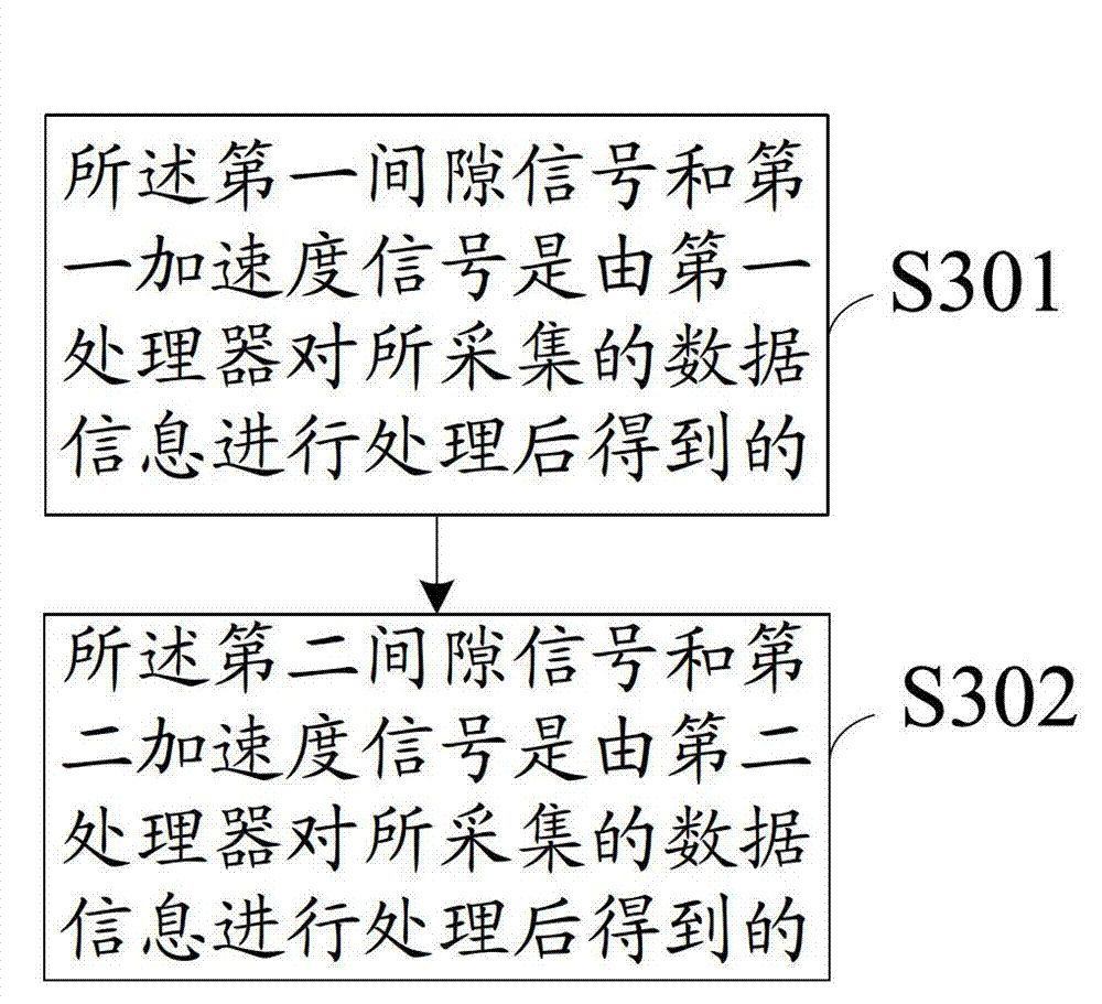
[0054] On the basis of Embodiment 1, how to further process the collected gap signal and acceleration signal in this embodiment, please refer to image 3 , which is another method flowchart of a suspension control method of the present invention, including:

[0055] S301: The first gap signal and the first acceleration signal are obtained by the first processor after processing the data information collected from the first suspension control point;

[0056] S302: The second gap signal and the second acceleration signal are obtained by the second processor after processing the data information collected from the second suspension control point.

[0057] Preferably, the first processor and the second processor are specifically FPGA chips capable of processing data in parallel.

[0058] What needs to be explained here is that when the data of two control points are connected to one processor for processing at the same time, the processing time of the processor will become longer...

Embodiment 3

[0066] On the basis of Embodiment 1 and Embodiment 2, combined with specific implementation scenarios, the technical solution of the present invention is described and analyzed in detail. see Figure 4 , which is a realization block diagram of a suspension control system of the present invention.

[0067] The sensor 403 and the sensor 404 respectively collect relevant data of the two suspension control points 401 and 402 of the electromagnet module on the same side of the train, including gap signals and acceleration signals.

[0068] The sensor 403 and the sensor 404 send the collected signals to the corresponding FPGA processors 405 and 406 for preprocessing through the 485 bus.

[0069] The FPGA processors 405 and 406 process the received multi-channel signals, generally speaking, three-way gap signals and two-way acceleration signals in parallel, and then discriminate an effective signal of one-way gap signal and an effective signal of one-way acceleration signal, and Va...


PUM


Abstract

An embodiment of the invention discloses a suspension control method which includes the steps: receiving a first gap signal and a first acceleration signal of a first suspension control point and receiving a second gap signal and a second acceleration signal of a second suspension control point; acquiring a first control signal and a second control signal according to the received signals; and simultaneously transmitting the first control signal to the first suspension control point and transmitting the second control signal to the second suspension control point, wherein the first control signal is used for controlling the suspension force of the first suspension control point, and the second control signal is used for controlling the suspension force of the second suspension control point. Therefore, acquired data of the two suspension control points of an electromagnet module on the same side of a train are transmitted to the same signal processor, two sets of control signals are acquired by comprehensively calculating the data of the two suspension control points, and the corresponding suspension control points are synchronously controlled, so that coupling of the two suspension control points of the electromagnet module on the same side of the train is eliminated when the suspension force is controlled.

Description

technical field [0001] The invention relates to the field of electromagnetic control, in particular to a levitation control method and device. Background technique [0002] The maglev train levitates the train through the electromagnetic force between the electromagnet and the steel rail. Each electromagnet module has multiple suspension control points. The suspension control system calculates the appropriate control command according to the data of the suspension control point measured by the suspension sensor to adjust the current passed by the electromagnet module, thereby adjusting the electromagnetic force of the electromagnet module to control the electromagnetic force. The floating and landing of the iron module can then adjust the suspension gap between the train and the rail to realize the suspension of the train. However, since the electromagnet module is a rigid body structure on the same side of the train, the two levitation control points on the same side will ...

Claims


Application Information

Patent Timeline
Patent Type & Authority Applications(China)
IPC IPC(8): B60L13/04
Inventor 彭奇彪佟来生罗京朱跃欧张文跃朱琳
Owner ZHUZHOU ELECTRIC LOCOMOTIVE CO
Learn More