
Method and system of network clock generation with multiple phase locked loops

a technology of network clock and lock loop, which is applied in the direction of digital transmission, data switching network, electrical equipment, etc., can solve the problems of limiting the ability to receive and transmit high-speed data signals along with traditional quality voice signals, access parts of existing access networks are not well-matched to the type of information, and user demand to shi

Inactive Publication Date: 2007-05-31
TELLABS BEDFORD
View PDF20 Cites 21 Cited by
  • Summary
  • Abstract
  • Description
  • Claims
  • Application Information

AI Technical Summary

Benefits of technology

[0007] A method and system according to an embodiment of the present invention generates a network quality clock signal in a communications system by synthesizing a first clock signal based on arrival rate of packets transmitted via a network link at a rate according to a network clock. The system then synthesizes a second clock signal based on the first clock signal. In one embodiment, the second clock signal has a frequency substantially the same as the network clock.

Problems solved by technology

The basic problem with transporting data over this voice-centric network, and, in particular, the local loop access part of the network, is that it is optimized for voice traffic, not data.
The voice-centric structure of the access network limits an ability to receive and transmit high-speed data signals along with traditional quality voice signals.
Simply put, the access part of the existing access network is not well-matched to the type of information it is now primarily transporting.
As users demand higher and higher data transmission capabilities, the inefficiencies of the existing access network will cause user demand to shift to other mediums of transport for fulfillment, such as satellite transmission, cable distribution, wireless services, etc.
These prior art DLC and FTTC systems suffer from several disadvantages.
First, these systems are costly to implement and maintain due to a need for sophisticated signal processing, multiplexing / demultiplexing, control, management and power circuits located in the HDT and the ONUs.
Purchasing, then servicing this equipment over its lifetime has created a large barrier to entry for many local loop service providers.
Scalability is also a problem with these systems.
Although these systems can be partially designed to scale to future uses, data types, and applications, they are inherently limited by the basic technology underpinning the HDT and the ONUs.
Absent a wholesale replacement of the HDT or the ONUs (a very costly proposition), these DLC and FTTC systems have a limited service life due to the design of intermediate electronics in the access loop.

Method used


Image

  • Method and system of network clock generation with multiple phase locked loops
  • Method and system of network clock generation with multiple phase locked loops
  • Method and system of network clock generation with multiple phase locked loops

Examples


Embodiment Construction

[0034] A description of preferred embodiments of the invention follows.

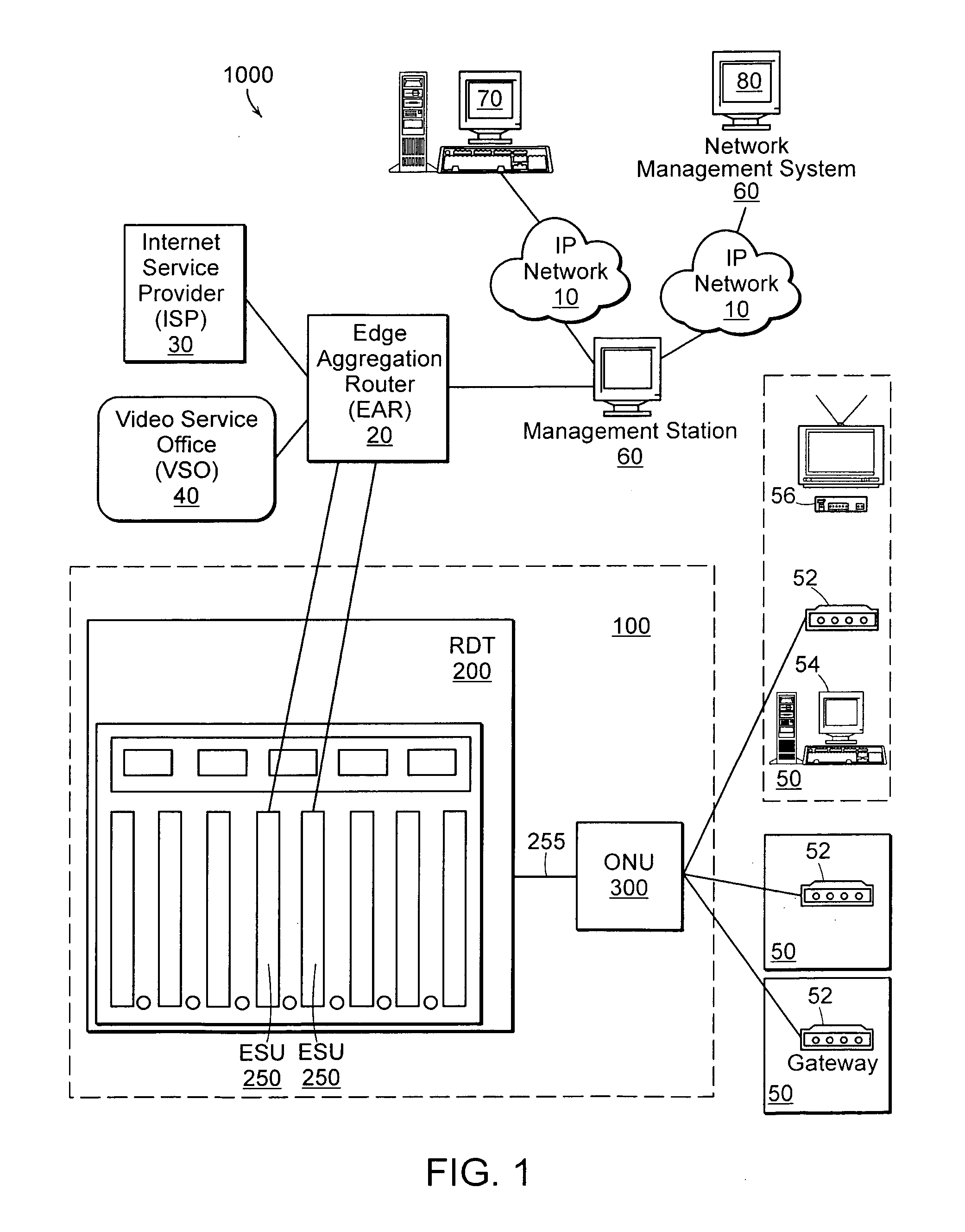
[0035] According to an embodiment of the present invention, a system or corresponding method increases available bandwidth for transmission of data, video, and audio to a customer, or sometimes a curb local to a customer, within a network. The system may include multiple network nodes. In one embodiment, first network node in the system converts a first optical communications signal to a corresponding first electrical signal with an asynchronous, packet-based format. The first network node processes the first electrical signal in a corresponding, asynchronous, packet-based manner, and routes the first electrical signal to a second network node among a group of secondary network nodes. This second network node converts the first electrical signal to a second optical signal and routes the second optical signal to a third network node among a group of tertiary network nodes. The third network node converts the seco...


PUM


Abstract

A method and system generates a network quality clock signal in a communications system by synthesizing a first clock signal based on arrival rate of packets transmitted via a network link at a rate according to a network clock. The system then synthesizes a second clock signal is then synthesized based on the first clock signal. In one embodiment, the second clock signal has a frequency substantially the same as the network clock.

Description

RELATED APPLICATIONS [0001] This application is a continuation-in-part of U.S. application Ser. No. 11 / 291,483 filed Nov. 30, 2005. This application also claims the benefit of U.S. Application No. 60 / 755,020, filed Dec. 29, 2005. The entire teachings of the above applications are incorporated herein by reference.BACKGROUND OF THE INTENTION [0002] Prior to growth in the public's demand for data services, such as dial-up Internet access, existing local loop access networks transported mostly voice information. In telephony, a local loop is defined as a wired connection from a telephone company's central office (CO) to its subscribers' telephones at homes and businesses. This connection is usually based on a pair of copper wires, typically in the form of twisted-pair wires. An existing access network typically includes numerous twisted-pair wire connections between a plurality of user locations and a central office switch (or terminal). These connections can be multiplexed in order to ...

Claims


Application Information

Patent Timeline
Patent Type & Authority Applications(United States)
IPC IPC(8): H04L12/56
CPCH04L12/24H04L12/2856H04L12/2885H04L12/4641H04L29/12103H04L41/00H04L41/0806H04L41/12H04L41/22H04L41/5061H04L61/1535H04L61/4535
Inventor KIMBROUGH, MAHLON D.GAINER, JAMES J.
Owner TELLABS BEDFORD
Learn More