
Extending sso for DHCP snooping to two box redundancy

Inactive Publication Date: 2007-05-31
CISCO TECH INC
View PDF12 Cites 130 Cited by
  • Summary
  • Abstract
  • Description
  • Claims
  • Application Information

AI Technical Summary

Benefits of technology

[0017] In another embodiment, the invention pertains to a computer system is operable to facilitate DHCP (dynamic host configuration protocol) Snooping data. The computer system includes one or more processors and one or more memory. The one or more processors and memory are configured for perfo

Problems solved by technology

However, use of a routing protocol is typically time consuming (e.g., to build the routing tables via routing discovery mechanisms), complex (e.g., to account for multiple changes in host configuration over time), and resource intensive (e.g., requiring large routing tables).
Unfortunately, if the gateway 206a fails, all of its underlying hosts need to be reconfigured.
This reconfiguration process can require significant amounts of time and temporary disruption in communication between a new gateway and a particular host can occur prior to reconfiguration of the particular host.
Although conventional redundancy protocols work well for most applications, problems may occur under certain applications.
When traffic comes from a particular MAC address that does not match the corresponding IP address for such binding, the gateway router determines that an attack or breach of security is in progress and does not allow such traffic to pass through the gateway to its destination.
Unfortunately DHCP Snooping currently may not work after a failover scenario.
When the active gateway fails, the binding information is lost for its mobile hosts.
Thus, security breaches may occur with the new active router since the new active router is not aware of valid MAC and IP address bindings for its hosts.
This problem becomes more complex when different active routers handle different VLAN's since each active router is learning different DHCP bindings for its particular VLAN.

Method used


Image

  • Extending sso for DHCP snooping to two box redundancy
  • Extending sso for DHCP snooping to two box redundancy
  • Extending sso for DHCP snooping to two box redundancy

Examples


Embodiment Construction

[0027] Reference will now be made in detail to a specific embodiment of the invention. An example of this embodiment is illustrated in the accompanying drawings. While the invention will be described in conjunction with this specific embodiment, it will be understood that it is not intended to limit the invention to one embodiment. On the contrary, it is intended to cover alternatives, modifications, and equivalents as may be included within the spirit and scope of the invention as defined by the appended claims. In the following description, numerous specific details are set forth in order to provide a thorough understanding of the present invention. The present invention may be practiced without some or all of these specific details. In other instances, well known process operations have not been described in detail in order not to unnecessarily obscure the present invention.

[0028] The following description includes examples of a redundant router group implementing Hot Standby Ro...


PUM


Abstract

Disclosed are mechanisms for facilitating the use of DHCP (dynamic host configuration protocol) binding data. In general, certain applications include mechanisms for intercepting data being sent from a node and then determining whether the data corresponds to a valid IP address and MAC address binding. Embodiments of the present invention provide mechanisms for sharing such DHCP binding data between routers (or other type of network devices) in a redundancy group so that any of the routers may take over the data inspection to validate DHCP bindings. In particular aspects of the invention, the DHCP binding data is validated in procedures related to DHCP snooping, dynamic ARP (address resolution protocol) inspection, and the like.

Description

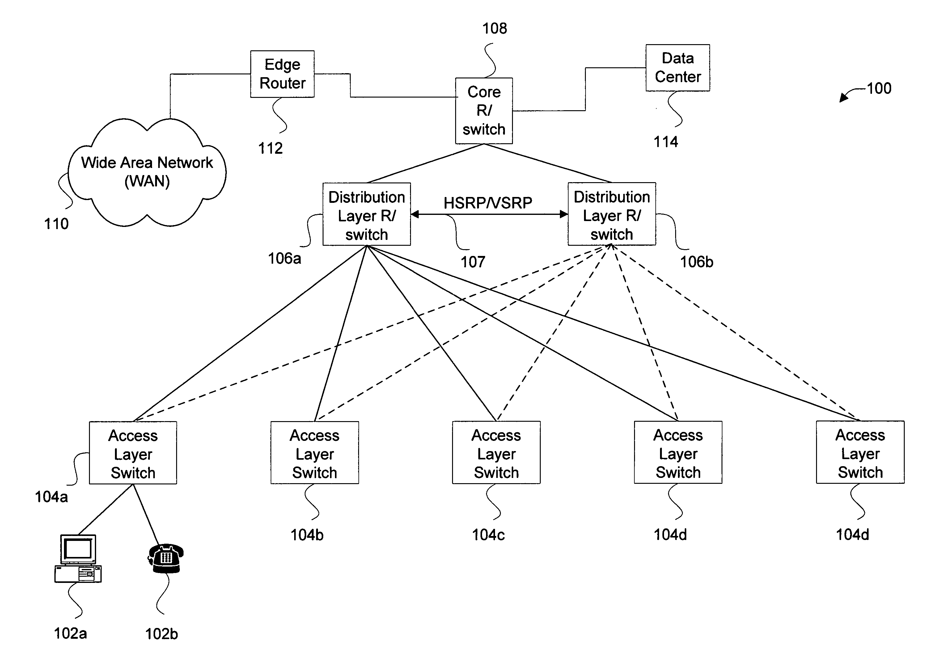
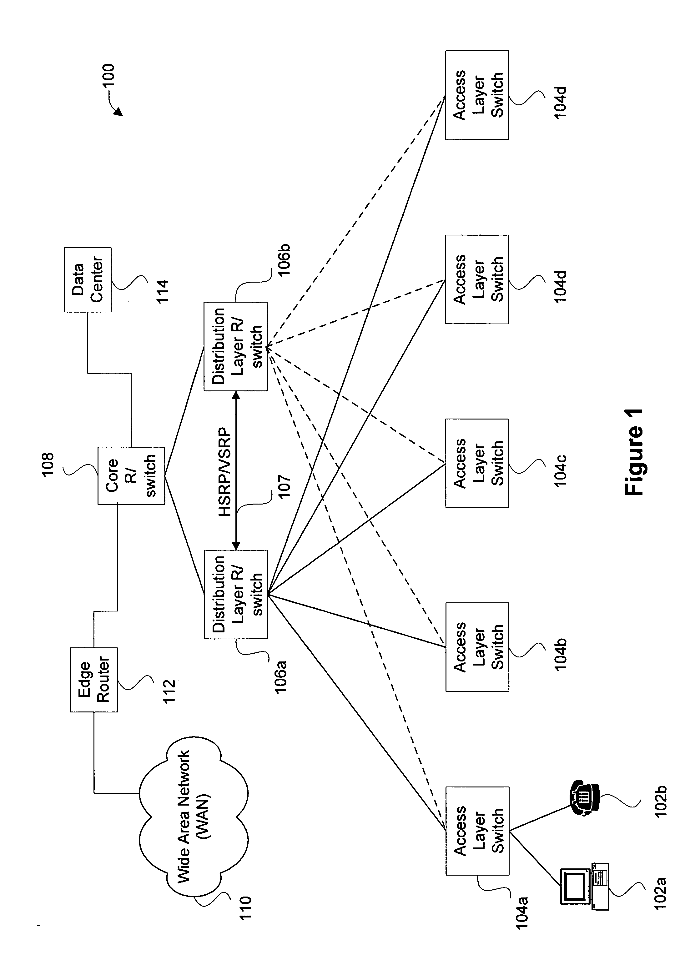
BACKGROUND OF THE INVENTION [0001] The present invention relates generally to computer network systems using a redundant router group. More particularly, it relates to mechanisms for facilitating DHCP (dynamic host configuration protocol) snooping, and the like, after failure in such a redundancy router group. [0002]FIG. 1 is a diagrammatic representation of an example enterprise system 100. As shown, the enterprise system 100 includes a plurality of access layer switches 104 that are each coupled to one or more end hosts. For instance, access switch 104a is coupled to computer system 102a and IP phone 102b. Typically, each access switch provides layer 2 bridging for a plurality of hosts (not shown for each switch). The access switches 104 are typically coupled to two or more distribution layer routers and switches 106. Each distribution layer router / switch 106 may provide layer 3 routing, as well as layer 2 bridging. These distribution layer routers / switches 106 are together couple...

Claims


Application Information

Patent Timeline
IPC IPC(8): H04L12/56H04L45/24H04L69/40H04L45/28H04L45/586
CPCH04L12/4641H04L45/04H04L45/22H04L45/28H04L45/586H04L49/552H04L69/40H04L61/5014H04L63/1466
Inventor KANEKAR, BHUSHAN MANGESHFOSCHIANO, MARCO ELIGIO
Owner CISCO TECH INC
Learn More