
Measurement transducer of vibration type

a measurement transducer and type technology, applied in the direction of mass flow measurement devices, measurement devices, instruments, etc., can solve the problems of only being able to compensate transverse forces of the same frequency in a very limited extent, and only with a very high technical effort, so as to improve the balance of the measurement transducer, reduce the mass, and improve the effect of disturbance resistan

Active Publication Date: 2007-05-31
ENDRESS HAUSER FLOWTEC AG
View PDF17 Cites 65 Cited by
  • Summary
  • Abstract
  • Description
  • Claims
  • Application Information

AI Technical Summary

Benefits of technology

[0045] An advantage of the invention is that by an, especially in comparison to the heavy counteroscillators proposed in U.S. Pat. No. 5,287,754, U.S. Pat. No. 5,705,754, U.S. Pat. No. 5,796,010 or U.S. Pat. No. 6,948,379, slight increase of the mass of the inner part, considerable improvements in the balance of the measurement transducer and, as a result, also its disturbance resistance, can be achieved. The measurement transducer of the invention is distinguished by its being very disturbance resistant, also relative to disturbing oscillations possibly coupled in via a connected pipeline. It has been found additionally that such a measurement transducer can have a significantly lower mass e.g. compared to a measurement transducer whose inner transverse forces are compensated in comparable quality by means of the simple mechanical low pass system mentioned in U.S. Pat. No. 5,287,754, U.S. Pat. No. 5,705,754, U.S. Pat. No. 5,796,010 or U.S. Pat. No. 6,948,379. Additionally, it can be embodied very compactly due to the dynamic oscillatory uncoupling. Therefore, the measurement transducer is suited especially also for measurements in pipelines having nominal diameters e.g. greater than 50 mm. Nevertheless, the measurement transducer is also well suited for measurements in pipelines having a nominal diameter of 40 mm or smaller.
is that by an, especially in comparison to the heavy counteroscillators proposed in U.S. Pat. No. 5,287,754, U.S. Pat. No. 5,705,754, U.S. Pat. No. 5,796,010 or U.S. Pat. No. 6,948,379, slight increase of the mass of the inner part, considerable improvements in the balance of the measurement transducer and, as a result, also its disturbance resistance, can be achieved. The measurement transducer of the invention is distinguished by its being very disturbance resistant, also relative to disturbing oscillations possibly coupled in via a connected pipeline. It has been found additionally that such a measurement transducer can have a significantly lower mass e.g. compared to a measurement transducer whose inner transverse forces are compensated in comparable quality by means of the simple mechanical low pass system mentioned in U.S. Pat. No. 5,287,754, U.S. Pat. No. 5,705,754, U.S. Pat. No. 5,796,010 or U.S. Pat. No. 6,948,379. Additionally, it can be embodied very compactly due to the dynamic oscillatory uncoupling. Therefore, the measurement transducer is suited especially also for measurements in pipelines having nominal diameters e.g. greater than 50 mm. Nevertheless, the measurement transducer is also well suited for measurements in pipelines having a nominal diameter of 40 mm or smaller.

Problems solved by technology

On the other hand, a significant disadvantage of the above-described measurement transducers lies in the fact that, because of the alternating lateral deflections of the vibrating, single measuring tube, oscillating transverse forces of the same frequency can be caused to act on the pipeline.
To this point in time, these transverse forces have only been able to be compensated to a very limited extent and only with a very high technical effort.
In contrast, those measurement transducers, especially those disclosed in U.S. Pat. No. 5,531,126 or U.S. Pat. No. 5,969,265, in the case of applications with media having densities fluctuating over wide ranges, especially in the case of different media following one after the other, and even when to only a slight degree, exhibit practically the same disadvantage as measurement transducers without counteroscillators, since the above-mentioned net resultant forces are also dependent on the density of the medium and consequently can be different from zero to a considerable degree.
A great disadvantage of such a measurement transducer is, among other things, however, that the counteroscillator mass required for achieving a sufficiently robust damping increases more than proportionately with the nominal diameter of the measuring tube.
Further investigations have, however, shown that, although with the decoupling mechanism proposed in U.S. Pat. No. 6,691,583 and U.S. Pat. No. 6,840,109, in principle, very good results are achievable with respect to disturbance resistance, the configurations disclosed there, nevertheless, exhibit bandwidths, which are too small for the decoupling mechanism and, as a result, may not yield satisfactory results with respect to the disturbance resistance of the measurement transducer when it comes to certain applications, especially in those applications involving medium densities fluctuating within very wide ranges.

Method used


Image

  • Measurement transducer of vibration type
  • Measurement transducer of vibration type
  • Measurement transducer of vibration type

Examples


Embodiment Construction

[0055] While the invention is susceptible to various modifications and alternative forms, exemplary embodiments thereof have been shown by way of example in the drawings and will herein be described in detail. It should be understood, however, that there is no intent to limit the invention to the particular forms disclosed, but on the contrary, the intention is to cover all modifications, equivalents, and alternatives falling within the spirit and scope of the invention as defined by the intended claims.

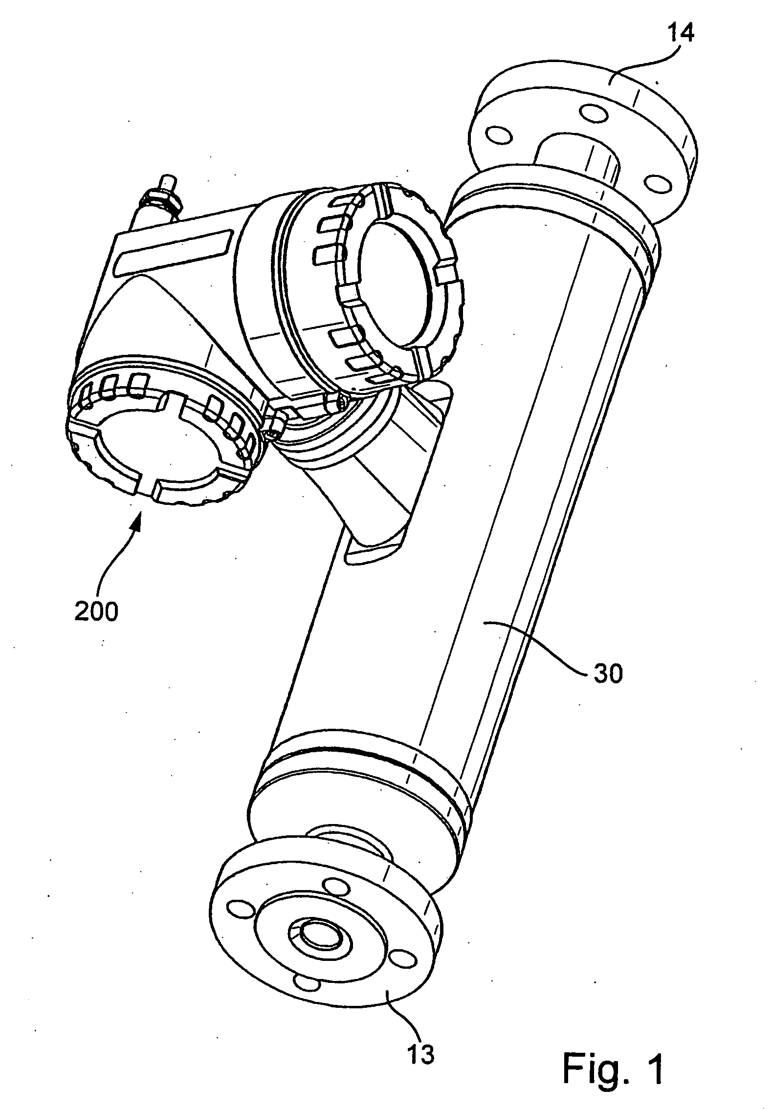
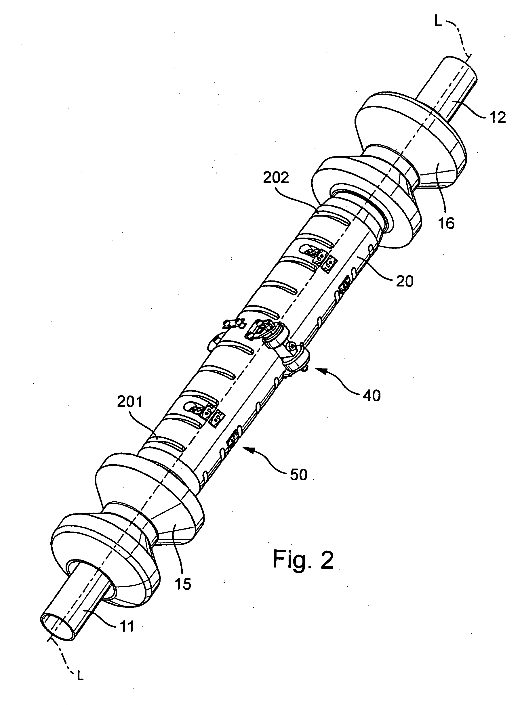
[0056] Shown in FIG. 1 is an inline measuring device insertable into a pipeline, for example, as a Coriolis mass flow measuring device, a density measuring device, a viscosity measuring device, or the like, which serves for measuring and / or monitoring at least one parameter, for example, a mass flow rate, a density, a viscosity, etc., of a medium flowing in the pipeline. The inline measuring device includes for such purpose a measurement transducer of vibration-type, through which t...


PUM


Abstract

The measurement transducer includes: A measuring tube vibrating at least at times during operation and serving for the conveying of a medium, wherein the measuring tube communicates with a pipeline via an inlet tube piece at an inlet end and an outlet tube piece at an outlet end; a counteroscillator, which is affixed to the measuring tube on the inlet end to form a first coupling zone and affixed to the measuring tube on the outlet end to form a second coupling zone; and a first cantilever for producing bending moments in the inlet tube piece and coupled with the inlet tube piece and the measuring tube essentially rigidly in the area of the first coupling zone and having a center of mass lying in the region of the inlet tube piece, as well as a second cantilever for producing bending moments in the outlet tube piece and coupled essentially rigidly with the outlet tube piece and the measuring tube in the region of the second coupling zone and having a center of mass lying in the region of the outlet tube piece. The measurement transducer of the invention is especially suited also for measuring tubes having large nominal diameters of more than 50 mm.

Description

FIELD OF THE INVENTION [0001] The invention relates to a measurement transducer of vibration-type, especially one suited for use in a Coriolis mass-flow meter. BACKGROUND OF THE INVENTION [0002] For determining a mass flow of a medium, especially a liquid flowing in a pipeline, often such measuring devices are used, which by means of a measurement transducer of vibration-type and a control and evaluation electronics connected thereto, create Coriolis forces in the medium and produce, derived from these forces, a measurement signal representing the mass flow. [0003] Such Coriolis mass-flow meters have been known for a long time and have established themselves well in industrial application. Thus, for example in EP-A 317 340, U.S. Pat. No. 5,398,554, U.S. Pat. No. 5,476,013, U.S. Pat. No. 5,531,126, U.S. Pat. No. 5,691,485, U.S. Pat. No. 5,705,754, U.S. Pat. No. 5,796,012, U.S. Pat. No. 5,945,609, U.S. Pat. No. 5,979,246, U.S. Pat. No. 6,006,609, U.S. Pat. No. 6,397,685, U.S. Pat. No....

Claims


Application Information

Patent Timeline
Patent Type & Authority Applications(United States)
IPC IPC(8): G01F1/84
CPCG01F1/8404G01F1/8409G01F1/8413G01F1/8418G01F1/8422G01F1/8427G01F1/849
Inventor BITTO, ENNIOECKERT, GERHARDLORENZ, RAINERRIEDER, ALFREDSCHUETZE, CHRISTIANFUCHS, MICHALANKLIN-IMHOF, MARTINDRAHM, WOLFGANGPROBST, LEONHARD
Owner ENDRESS HAUSER FLOWTEC AG
Learn More