Active isolation system for fuel cell

Inactive Publication Date: 2007-05-24
GM GLOBAL TECH OPERATIONS LLC
View PDF5 Cites 9 Cited by
  • Summary
  • Abstract
  • Description
  • Claims
  • Application Information

AI Technical Summary

Benefits of technology

[0004] Accordingly, the present invention provides a fuel cell system including a fuel cell having coolant flowing therethrough and a high voltage direct current (HVDC) bus interconnected with the fuel cell. An active isolation circuit includes a first/second or multiple current sensors

Problems solved by technology

The low-conductivity or isolating coolants typically have significant performance disadvantages when compared to higher conductivity coolants, such as automotive (i.e. water and glycol-based) coolants.
For example, the isolating coolants typically have low heat capacity, low heat conductivity and high viscosity (e.g. oil).
The isolating coolants therefore adversely impact system power density, radiator size, radiator fan size, and / or coolant pump power.
The low-conductivity coolants may also pose various environmental constraints.
The low-conductivity coolants lack anti-freeze characteristics and / or may cause corrosion (e.g., de-ionized water).
Contaminations in the coolant system also tend to increase the conductivity of a low-conductivity coolant over time and hence isolation gets worse.

Method used


Image

  • Active isolation system for fuel cell
  • Active isolation system for fuel cell
  • Active isolation system for fuel cell

Examples


Embodiment Construction

[0015] The following description of the preferred embodiments is merely exemplary in nature and is in no way intended to limit the invention, its application, or uses. For purposes of clarity, the same reference designations will be used in the drawings to identify similar elements.

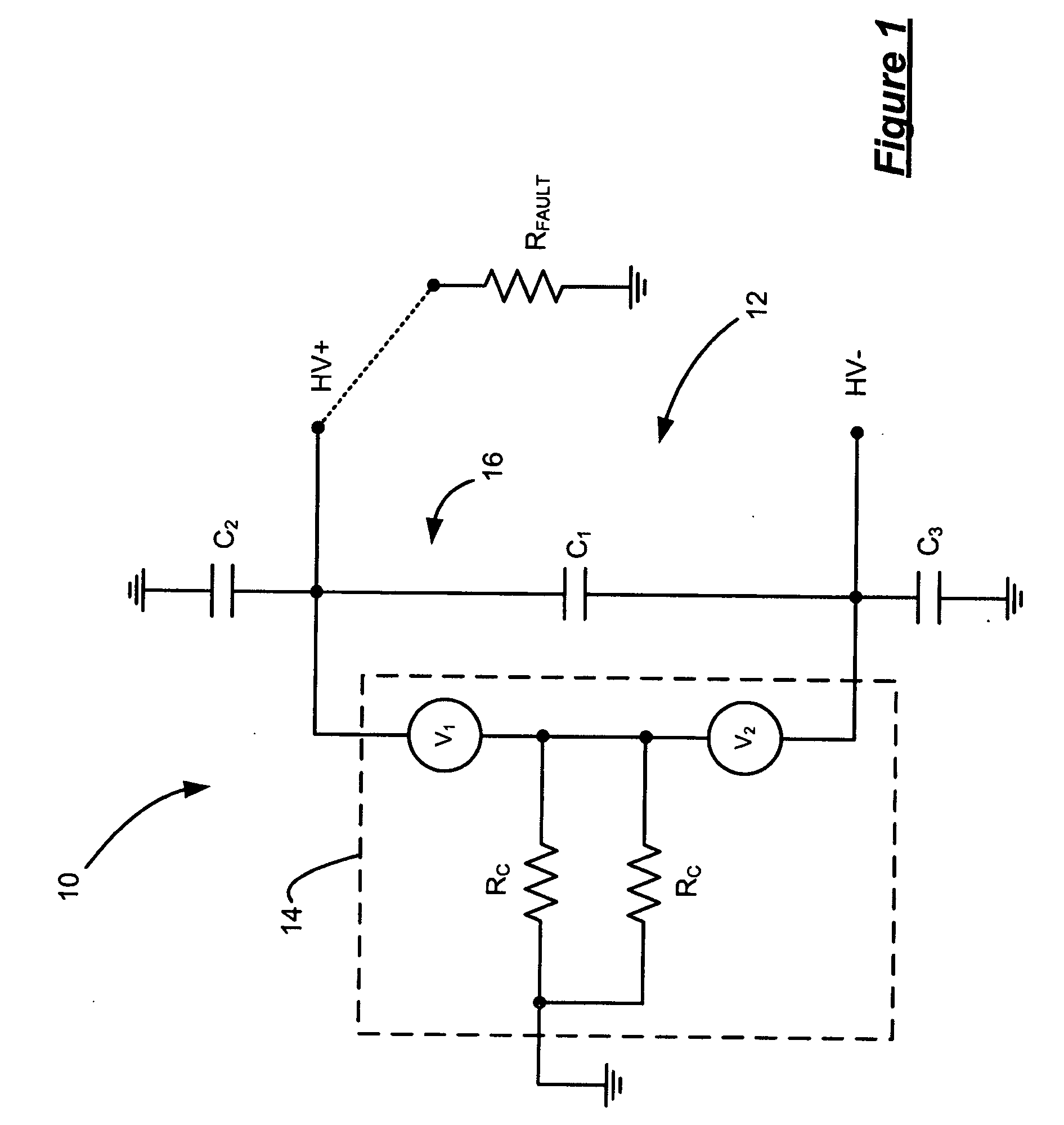
[0016] Referring now to FIG. 1, a fuel cell system 10 includes a high voltage direct current (HVDC) power bus 12 and a fuel cell stack 14. The fuel cell stack 14 is represented as two voltage sources V1 and V2. Exemplary values for V1 and V2 are 200V, although other values may be used. Assuming 200V for V1 and V2, the total voltage across the fuel cell stack 14 is 400V. The fuel cell stack 14 includes conductive coolant flowing through manifolds. The coolant entering / exiting the fuel cell is indicated as parallel resistors Rc. Exemplary values for the resistors Rc are 20 kΩ each or 10 kΩ total. As the coolant may enter (exit) the fuel cell stack through manifolds at any defined points of the fuel cell, t...


PUM


Abstract

A fuel cell system includes a fuel cell having conductive coolant flowing there through and a high voltage direct current (HVDC) bus interconnected with the fuel cell. An active isolation circuit includes coolant fault current sensors that detect a fault current (also called residual current) in the coolant and generates a fault signal when the fault current is detected. A switching circuit compensates and redirects the fault current based on the fault signal, providing active fault current limitation thereby.

Description

FIELD OF THE INVENTION [0001] The present invention relates to fuel cells or other automotive HVDC sources and more particularly to voltage and / or current isolation systems for conductive (i.e., non-isolating) fluid cooled fuel cell stacks. BACKGROUND OF THE INVENTION [0002] Fuel cell stacks operate at relatively high voltage levels and higher temperatures. Liquid flowing through a coolant loop is typically used to control the temperature of the fuel cell stack. The coolant loop typically includes radiators, pumps, tubes and / or other components. To improve safety, steps are typically taken to isolate the high voltage levels of the fuel cell stack from the coolant flowing in the coolant loops. In other words, to provide electrical isolation, the coolant loops should be either electrically isolated or non-conductive coolant should be used. [0003] Current approaches employ very low-conductivity or isolating coolant and long / thin isolating coolant tubes. For example, the low-conductivit...

Claims


Application Information

Patent Timeline
IPC IPC(8): H01M8/04G01R31/02
CPCH01M8/04537H01M8/04664H01M8/04865H01M8/04895Y02E60/50H01M8/04029H01M8/04485
Inventor RAISER, STEPHEN
Owner GM GLOBAL TECH OPERATIONS LLC
Why Eureka
Try Eureka