
Rotor blade for a wind energy installation

Inactive Publication Date: 2007-05-17
DAUBNER & STOMMEL BAU WERK PLANUNG
View PDF12 Cites 45 Cited by
  • Summary
  • Abstract
  • Description
  • Claims
  • Application Information

AI Technical Summary

Benefits of technology

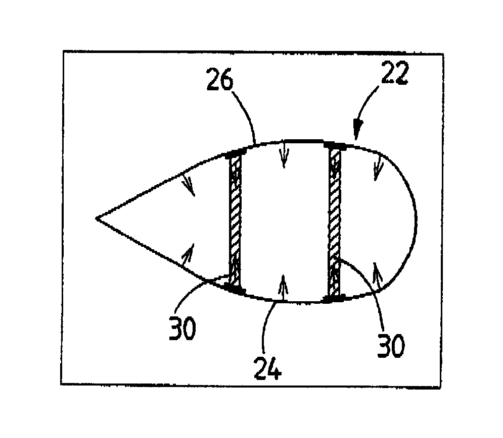
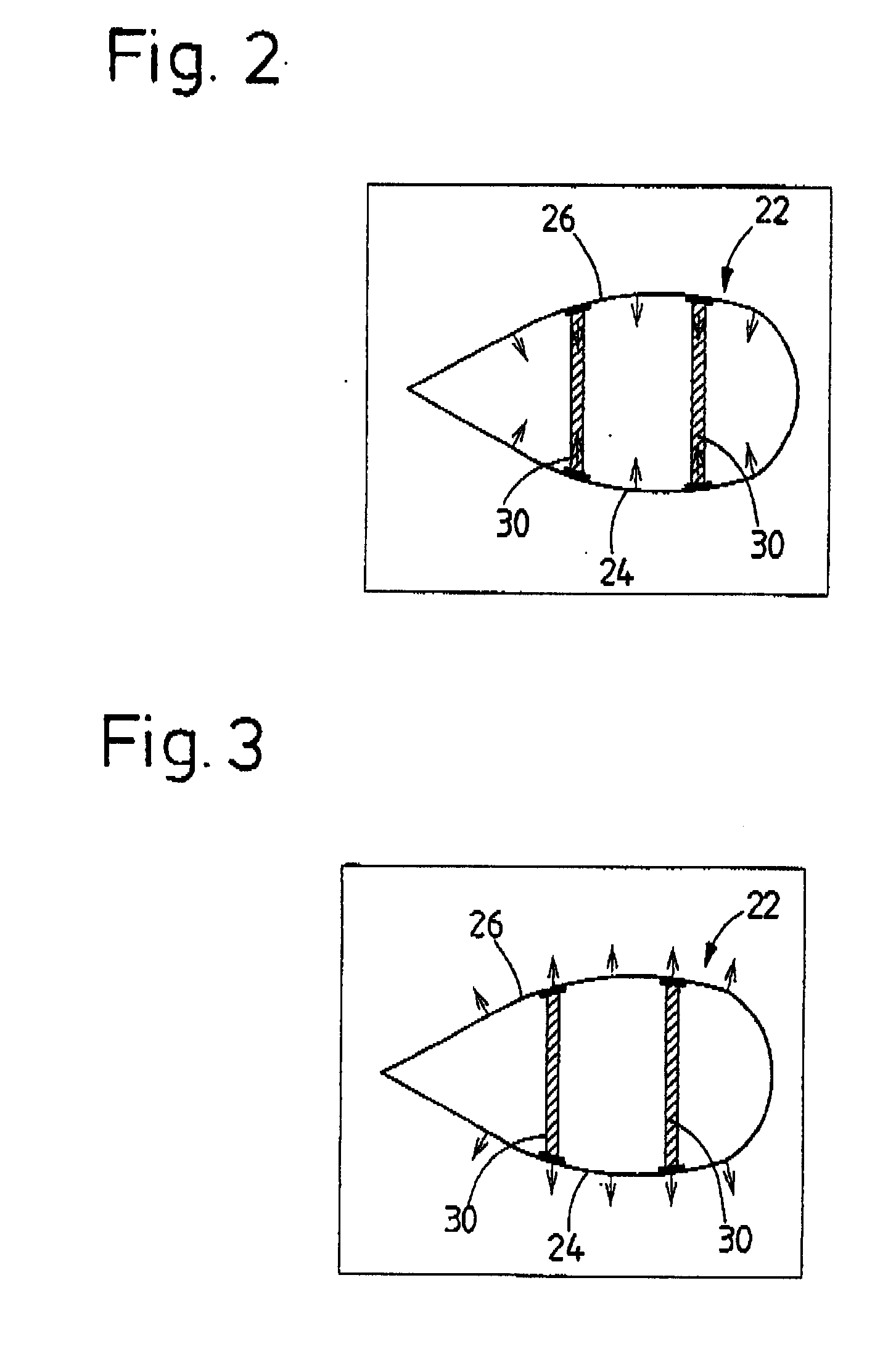
[0012] The cavity in the rotor blade can have an appropriate gas, which is at an increased pressure or at a vacuum pressure, applied to it even during its production by means of a pressure source, in particular a compressor, or a vacuum-pressure source, in particular a pump. Air is expediently considered for this purpose. However, it is also possible to provide for inert gases to be used, for example as an additional precaution against internal corrosion processes on the rotor blade.
[0014] Inlet and / or outlet openings such as these allow the cavity in the rotor blade to be filled with—in particular additional—gas, or gas to be allowed out in order to increase or to reduce the pressure in the cavity in the rotor blade during operation, that is to say when the rotor blade is arranged on a rotor of a wind energy installation.
[0017] This embodiment of the invention is a method is specified for operation of a wind energy installation having a rotor blade of the type described above, in which the actual pressure and / or actual humidity and / or the actual temperature of the gas which is located in the cavity of the rotor blade are / is measured, with the pressure within the cavity being increased or decreased, and / or the gas within the cavity being at least partially, but preferably completely, replaced as a function of the actual pressure and / or the actual humidity and / or the actual temperature. This ensures that external temperature fluctuations in the vicinity of the wind energy installation, which lead to pressure fluctuations within the rotor blade cavity, can be compensated for.

Problems solved by technology

The rotor blades for wind energy installations are subject to high loads.
Over the course of an assumed operating life of, for example, twenty years the rotor blades rotate at least 300 to 500 million times. Frequent alternating bending loads, in particular, occur during this process and have an extremely negative effect on the life of the individual rotor blade.

Method used


Image

  • Rotor blade for a wind energy installation
  • Rotor blade for a wind energy installation
  • Rotor blade for a wind energy installation

Examples


Embodiment Construction

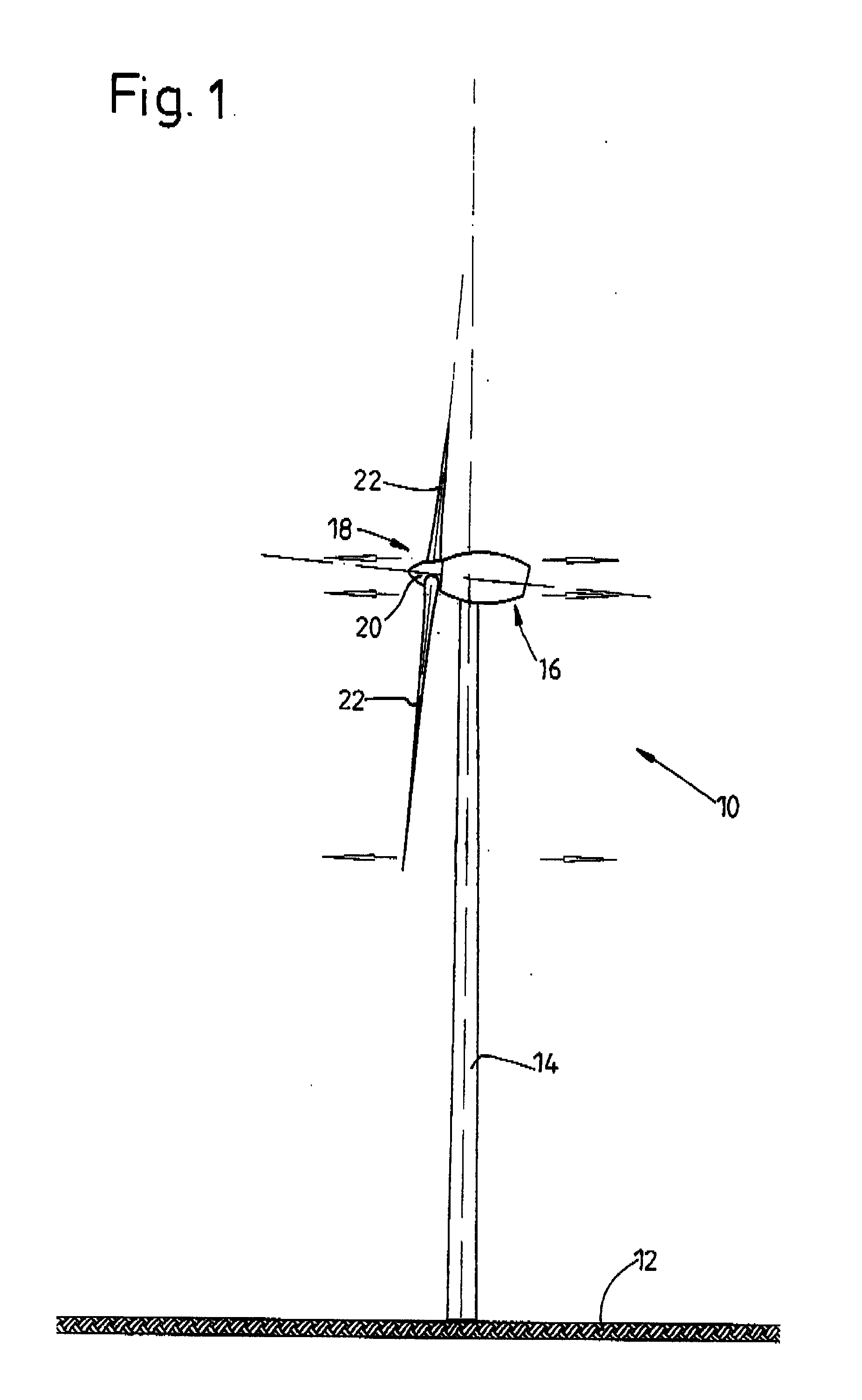
[0026]FIG. 1 illustrates a wind energy installation 10 which has a pod 16, which is arranged at the top of the tower, at the upper end of a vertical tower 14 which is arranged on a horizontal foundation 12. As those skilled in the art in this field know, a wide range of embodiments are feasible for the detailed design of a tower for a wind energy installation. The invention is, of course, not restricted to the truncated-conical form of the tower 14 described in the drawing.

[0027] A rotor 18 is arranged at an end of the pod 16 facing the wind, and has a hub 20. Three rotor blades 22 are connected to the hub 20, with the rotor blade roots of the rotor blades 22 being inserted into corresponding openings in the hub 20, and being connected to it in a known manner.

[0028] The rotor 18 rotates about an axis which is inclined slightly upwards with respect to the horizontal. As soon as wind strikes the rotor blades 22, the rotor 18 together with the rotor blades 22 is caused to rotate abou...


PUM


Abstract

The invention relates to a rotor blade (22) for a wind energy installation (10), with the rotor blade (22) having at least one cavity (28). The cavity (28) is sealed to be gas-tight and is filled with gas, in particular air, in order to prestress the rotor blade (22), with the pressure of the gas being greater than or less than the average air pressure to be expected at the point of use of the rotor blade.

Description

STATEMENT OF RELATED APPLICATIONS [0001] This patent application claims priority on German Patent Application No. 10 2005 054 594.7, having a filing date of 14 Nov. 2005, which is incorporated herein in its entirety by this reference. BACKGROUND OF THE INVENTION [0002] 1. Technical Field [0003] The present invention relates to a rotor blade for a wind energy installation, with the rotor blade having at least one cavity. The invention also relates to a method for operation of a wind energy installation having a rotor which can be driven by wind and has at least one rotor blade of the abovementioned type, having a generator for conversion of the mechanical energy of the rotor to electrical energy, and having a tower on which the rotor is arranged. [0004] 2. Related Art [0005] The rotor blades for wind energy installations are subject to high loads. Over the course of an assumed operating life of, for example, twenty years the rotor blades rotate at least 300 to 500 million times. Freq...

Claims


Application Information

Patent Timeline
IPC IPC(8): B64C11/24
CPCF03D1/0675F03D1/0683Y02E10/721Y02E10/72
Inventor STOMMEL, MATTHIAS
Owner DAUBNER & STOMMEL BAU WERK PLANUNG
Learn More