
Combined mobile container inspection system with low target

Active Publication Date: 2007-05-17
NUCTECH CO LTD +1
View PDF5 Cites 78 Cited by
  • Summary
  • Abstract
  • Description
  • Claims
  • Application Information

AI Technical Summary

Benefits of technology

[0005] Accordingly, the present invention has been made to overcome the above mentioned problems, it is an object of the invention to provide a combined mobile container inspection system, with the characteristics of wider scanning range, easy installation, flexibilities of movement, high efficiency, lower cost, high imaging quality.
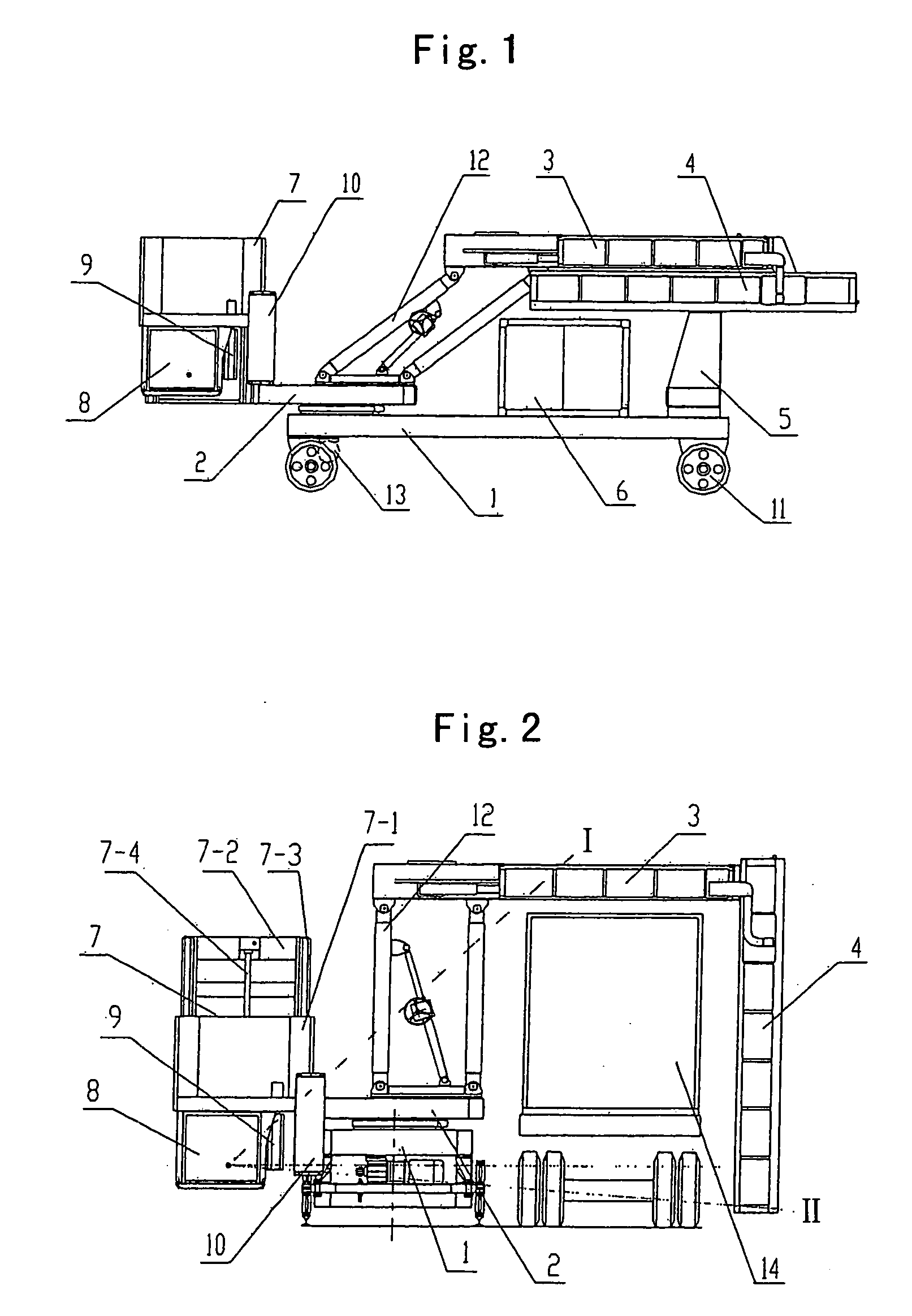
[0013] Therefore, the height of the radiation source provided on the sliding deck is adjustable due to the provision of a stepless positioning sliding deck on the rotatable deck according the present invention, therefore, the radiation range is enlarged, avoiding scanning dead corner. In addition, each part of the system can be of a mechanical modular structure, which makes the installation and debugging of the system easier, and also have the advantages of convenience, stability, high efficiency, low cost and provision of high quality images.

Problems solved by technology

The built-on vehicle movable container inspection system is typically a vehicle on which all the scanning, detecting and controlling devices are carried, or two vehicle of which one is installed with the scanning and detecting devices, the other with the controlling device to separate human from harmful radiation source, but the detection range is confined due to the vehicle configuration, and the devices adjustment is difficult.
The inspection device, however, can not inspect the chassis of the vehicle, and is restricted when a vehicle with special height or parking deviation has dead angle.
Moreover, site transferring lasts a long time, for example, about four weeks.
However, since vehicle chassis is still being used in the system, the device installation adjustment is difficult due to the vehicle structure confinements.

Method used


Image

  • Combined mobile container inspection system with low target
  • Combined mobile container inspection system with low target

Examples


Embodiment Construction

[0017] Reference will no be made in detail to the embodiments of the present invention, examples of which are illustrated in the accompany drawings, wherein like reference numerals refer to like elements throughout. The embodiments are described below so as to explain the present invention by referring to the figures.

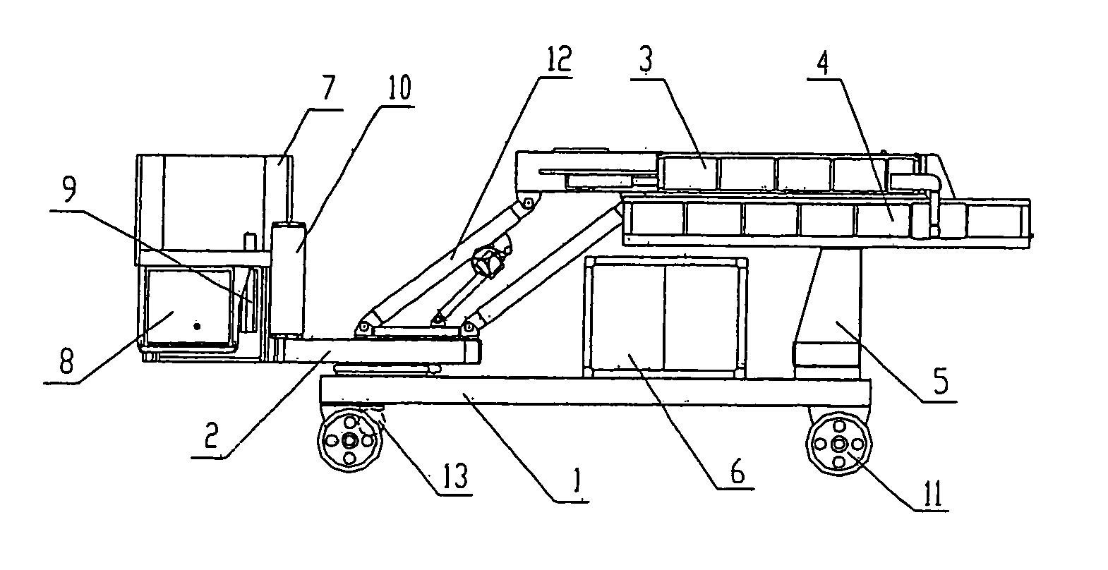
[0018] As shown in FIGS. 1-2, the combined mobile container inspection system with low target according to the present invention comprises a radiation source 8, which can adopt a linear electron accelerator or a radioactive isotope, a chassis 1 and a remote control device. One end of the chassis 1 is provided with a rotatable deck 2, which can moves in opposite direction, the other end thereof is provided with an auxiliary bracket 5 that can support a vertical upright arm 4 when it is parallels to the horizontal cross arm 3. when the vertical upright arm 4 is parallel to the horizontal cross arm 3, the system is in an instable state, and when the system is in a scannin...


PUM


Abstract

A combined mobile container inspection system, comprising: a radiation source; a chassis; a rotatable deck provided at an end of the upper surface of said chassis and rotatable with respect to said chassis, provided with a parallelogram bracket formed by a hingedly-connected four-bar linkage mechanism, wherein the cross link of the parallelogram bracket extends to form a horizontal cross arm with detectors, the other end of said horizontal cross arm is connected with a vertical upright arm, which is vertical or parallel to said horizontal cross arm; and a sliding deck provided at the rear end of the rotatable deck and movable upwardly and downwardly, said sliding deck is provided, in turn, with the radiation source, the X-ray therefrom is always right in the face of the detectors provided in the horizontal cross arm and vertical upright arm, calibrator and collimator.

Description

TECHNICAL FIELD [0001] The present invention relates to the field of radiation scan imaging detection technology, especially to a combined mobile container inspection system with low target. TECHNOLOGY BACKGROUND [0002] Container inspection system is essentially composed by a radiation source generating X-ray of high energy and detector arrays receiving the X-rays penetrating the container. The density distribution of the objects contained in the container is exhibited and obtained by the intensity variation of the X-ray penetrating through the container into the detectors, with the X-ray intensity being converted into grey level of an image, when the container passes the X-ray beams. Conventionally, the container inspection system is divided into a fixed container inspection system, a built-on vehicle movable container inspection system and a combined mobile container inspection system etc. The fixed container inspection system can achieve stable image quality whereas it occupies l...

Claims


Application Information

Patent Timeline
IPC IPC(8): G01N23/04G01V5/00
CPCG01N23/04G01V5/0008G01V5/20G01N23/02
Inventor HU, HAIFENGWU, YUCHENGSUN, SHANGMINCHEN, ZHIQIANGYANG, GUANGBAI, ZHENGYULIU, RONGXUANYANG, HONGLIANGSU, JIANJUNWANG, JIANTAOHAN, YANJUNHU, BINSONG, QUANWEIJIANG, NANPENG, HUALI, JIANMINSHEN, WANQUANLIANG, ZHIZHONG
Owner NUCTECH CO LTD
Learn More