Modular illuminator for a scanning printer

Inactive Publication Date: 2007-05-17
WHITNEY THEODORE ROBERT
View PDF10 Cites 4 Cited by
  • Summary
  • Abstract
  • Description
  • Claims
  • Application Information

AI Technical Summary

Benefits of technology

[0020] Use of a pulsed source of whatever type recognizes that each exposed point at the format is the integrated sum of partial exposure received from many source pulses. The source must operate at a pulse rate sufficiently high that no exposure effect of the pulsing can be seen. Thus, in the case of the Whitney '020 printer design configuration, use of a pulsed source operating at 4000 pulses per second is fine, but use...

Problems solved by technology

Excimer laser wavelengths, or indeed any wavelengths below about 330 nm., present special problems with respect to reflectivity, and where an exci...

Method used


Image

  • Modular illuminator for a scanning printer
  • Modular illuminator for a scanning printer
  • Modular illuminator for a scanning printer

Examples


Embodiment Construction

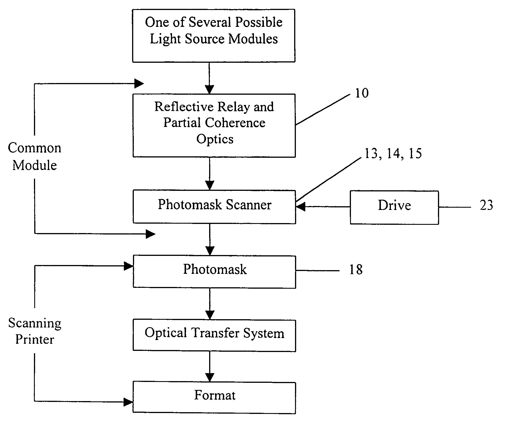
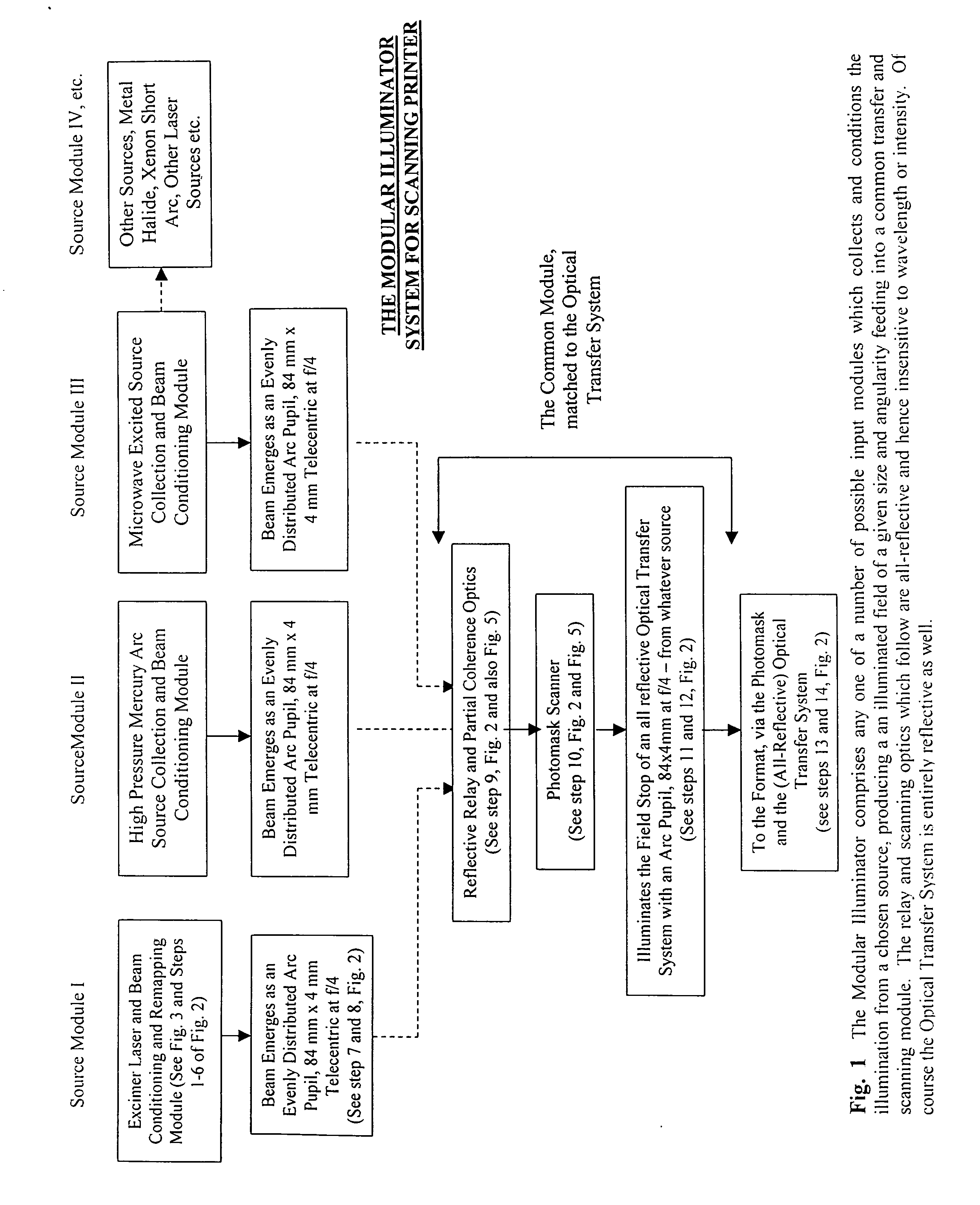
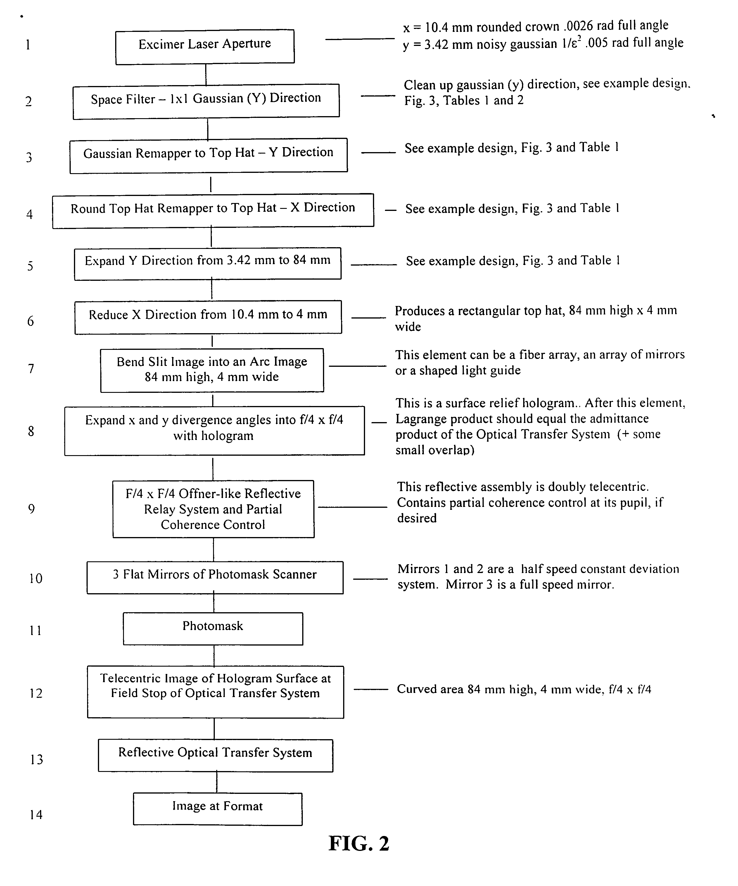
[0031] To illustrate the principle of the modular illuminator, I choose a design example based upon the downstream parameters of the printer described in Whitney '020. The 1-to-1 Offner-like reflective Optical Transfer System of that design has an arc shaped field stop, 84 mm. high, 4 mm. wide. The input optics must be telecentric and have a solid angle of admittance of f / 4×f / 4. The etendue of the Optical Transfer System in that design, using small angle approximations, is about:

8.4 cm The height of the illuminated input field×0.4 cm The width of the illuminated input field×0.25 rad The angular subtence of the width of the pupil as seen from the input field.×0.25 rad The angular subtence of the height of the pupil as seen from the input field.×π / 4 Conversion from a square to a circular pupil =0.165 cm2ster

This is the approximate etendue of the Optical Transfer System, the imaging optical assembly described in Whitney '020.

[0032] An excimer laser is chosen as an illumination sourc...


PUM


Abstract

Disclosed herewith is a system and method for building an illuminator for a scanning printer. The design is modular enabling any of a number of different sources to be used with common partial coherence and scanning optics. The illuminated field, moves across the photomask in synchronism with the motion of the scanning printer, preserving telecentricity, entendue and optical distance invariance as it scans.

Description

REFERENCE TO PRIOR APPLICATION [0001] This invention claims priority from Provisional Application Ser. No. 60 / 737,784 filed Nov. 17, 2005, and entitled “a Modular Illuminator for a Scanning Printer”.FIELD OF THE INVENTION [0002] This invention describes a modular illuminator optical system that will condition and remap the radiation output from various illumination sources and redirect the suitably modified light energy into the optical transfer system of a scanning printer. More particularly this invention uses as an example a modular illuminator which would be suitable for use with a printer such as that described in Whitney “ROLL PRINTER WITH DECOMPOSED RASTER SCAN AND X-Y DISTORTION CORRECTION” U.S. Pat. No. 7,130,020 B2 issued Oct. 31, 2006, hereinafter referred to as Whitney '020, incorporated herein by reference. BACKGROUND OF THE INVENTION [0003] Any given scanning printer is employed for a specific exposure purpose and consequently will have specific exposure requirements a...

Claims


Application Information

Patent Timeline
IPC IPC(8): G03B27/54
CPCG02B27/0911G02B27/0966G03B21/20G03B27/54G03F7/70358
Inventor WHITNEY, THEODORE ROBERT
Owner WHITNEY THEODORE ROBERT
Why Eureka
Try Eureka