
Lock-up clutch mechanism

a technology of locking mechanism and clutch, which is applied in the direction of interengaging clutch, fluid coupling, gearing, etc., can solve the problems of affecting affecting the transmission efficiency of the transmission device, and affecting the comfort of the vehicle, so as to improve the sealing ability of the interface, prevent the occurrence of judder, and improve the sealing effect of the interfa

Inactive Publication Date: 2007-05-17
NSK WARNER
View PDF6 Cites 8 Cited by
  • Summary
  • Abstract
  • Description
  • Claims
  • Application Information

AI Technical Summary

Benefits of technology

[0012] Accordingly, an object of the present invention is to provide a lock-up clutch mechanism with a simple construction, which can make face pressure of a friction surface in a circumferential direction more uniform, thereby preventing occurrence of judder and enhancing a sealing ability of an interface to increase a torque transmitting capacity.
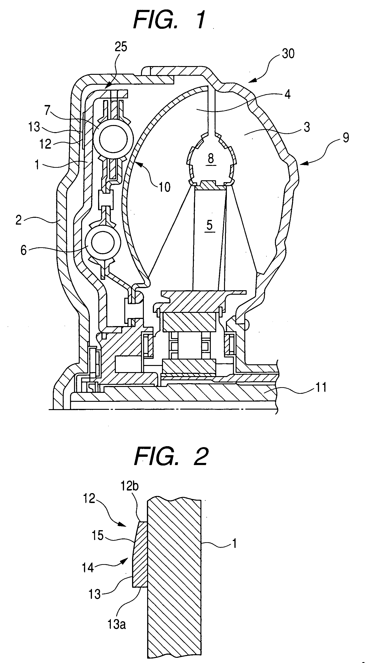
[0014] Since the friction material is provided with the outer peripheral friction surface engaged at the initial stage of engagement between the lock-up piston and the front cover and the inner peripheral friction surface engaged upon the tightening and the outer peripheral friction surface has the taper with respect to the inner peripheral friction surface and the inner peripheral friction surface and the outer peripheral friction surface are subjected to the cutting operation, a contacting condition at an interface between the lock-up friction material and a contact area of the front cover can be maintained to a good (uniform) state, with the result that a judder suppressing ability is enhanced by reducing contact unstable factors during the sliding movement and the increase in a reaction force caused by the urging pressure from the interface is suppressed by enhancing a sealing ability of the interface, thereby enhancing the capacity by using the urging force effectively.

Problems solved by technology

In torque converters used in automatic transmissions, although smooth starting, acceleration and deceleration can be achieved, since a power is transmitted via fluid, a transmitting efficiency is worsened.
In general, in the lock-up clutch, self-exciting vibration referred to as judder may be generated, thereby worsening comfort of the vehicle considerably.
The imbalance of the face pressure distribution is greatly influenced by accuracy of the friction surface, and, thus, there arises dispersion in the circumferential direction of the friction surface by slight undulation of a piston of the lock-up clutch and / or strain of attaching bolts for a drive plate provided on a front cover.
However, since the generation of the judder is greatly based on the imbalance of the face pressure distribution on the friction surface in the circumferential direction during the slipping, in the techniques disclosed in the Japanese Patent No. 315721 and the Japanese Patent Application Laid-Open No. 2004-11710, the judder could not necessarily be suppressed satisfactorily.
Further, it was difficult to obtain the greater torque transmitting capacity.
In this case, the entire surface of the lining to be contacted remains a configuration obtained when it is stuck or adhered, and thus, there is roughness or undulation on the surface of the friction material.
From this condition, if the friction material is engaged with or tightened to an opponent member, there is a danger of generating local areas where avoid is created between the friction material and the opponent member and local areas where higher contact pressure is created between the friction material and the opponent member.
As a result, a contacting condition at the interface between the friction material and the opponent member becomes unstable to generate the judder easily, and a sealing ability of the interface is worsened, thereby reducing the capacity.

Method used


Image

  • Lock-up clutch mechanism
  • Lock-up clutch mechanism

Examples


Embodiment Construction

[0019] Now, an embodiment of the present invention will be fully explained with reference to the accompanying drawings. In the drawings, the same elements or members are designated by the same reference numerals. Further, it should be noted that an embodiment which will be described hereinbelow is merely exemplary and does not limit the present invention in all senses.

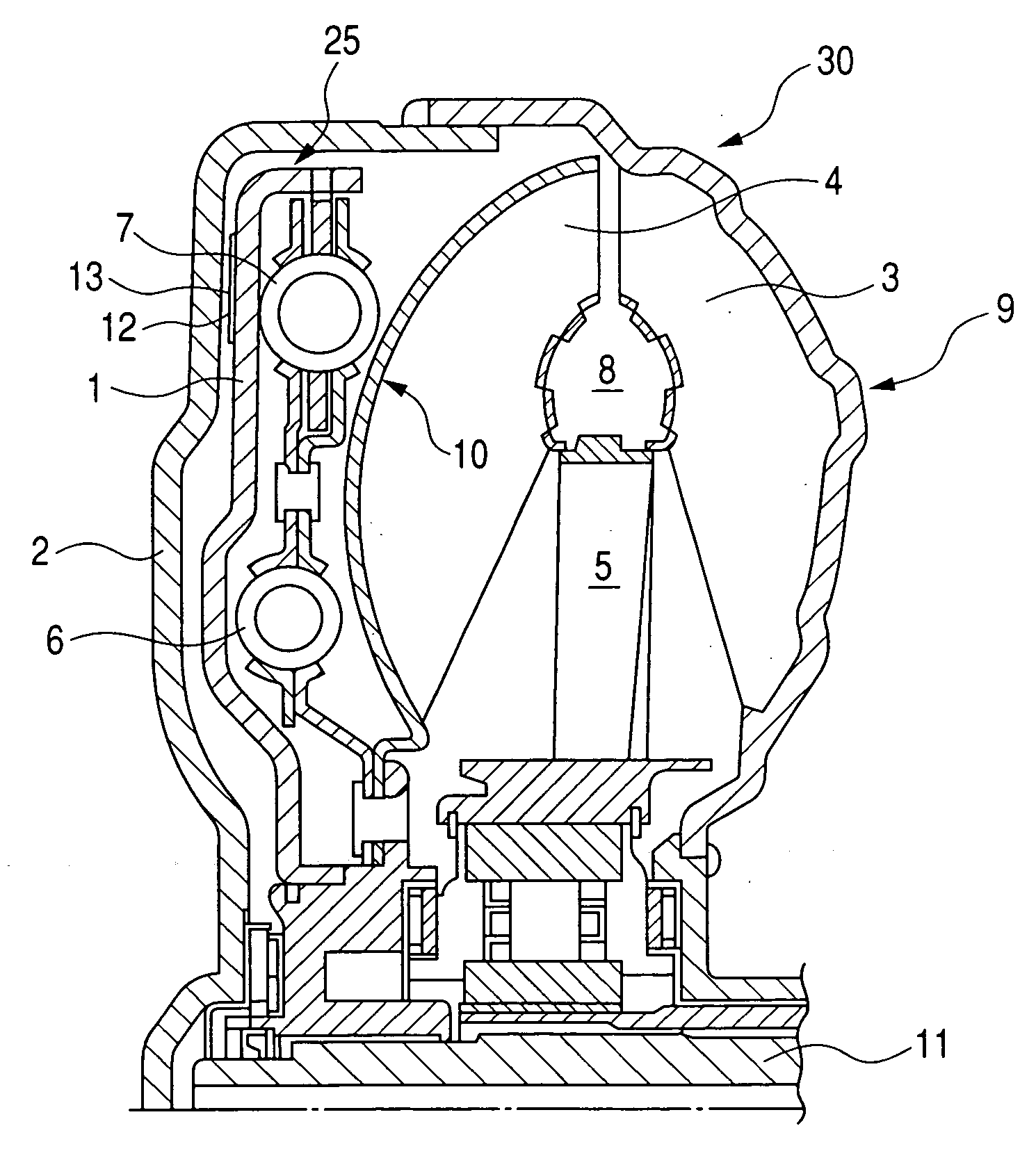
[0020]FIG. 1 is an axial partial sectional view of a torque converter 30 having a lock-up clutch mechanism according to the present invention, showing a released condition of a lock-up clutch. The torque converter 30 comprises a front cover 2 constituting a part of a housing of the torque converter 30, an impeller 9 as a donut-shaped vane wheel secured to the front cover 2, a turbine 10 as a donut-shaped vane wheel having blades or vanes opposed to vanes of the impeller 9, and a stator 5 rotatably provided between the impeller 9 and the turbine 10. The impeller 9, turbine 10 and stator 5 constitute a main body of the ...


PUM


Abstract

The present invention provides a lock-up clutch mechanism for a torque converter, comprising a lock-up piston and a front cover opposed to the lock-up piston and wherein a friction material having a friction surface is secured to one of the lock-up piston and the front cover, and the friction surface includes an outer peripheral friction surface which is engaged at an initial stage of engagement between the lock-up piston and the front cover and an inner peripheral friction surface which is engaged upon tightening, and the outer peripheral friction surface has a taper with respect to the inner peripheral friction surface, and the inner peripheral friction surface and the outer peripheral friction surface are subjected to a cutting operation.

Description

BACKGROUND OF THE INVENTION [0001] 1. Field of the Invention [0002] The present invention relates to a lock-up clutch mechanism used with a torque converter of an automatic transmission for a vehicle, and more particularly, it relates to an improvement in a friction sliding surface of the lock-up clutch mechanism. [0003] 2. Related Background Art [0004] In torque converters used in automatic transmissions, although smooth starting, acceleration and deceleration can be achieved, since a power is transmitted via fluid, a transmitting efficiency is worsened. Thus, there has been proposed a technique in which, if a speed of the vehicle exceeds a predetermined value, in order to reduce energy loss and to enhance reduction of fuel consumption, a lock-up clutch mechanism having a lock-up clutch is operated to directly connect an engine to drive wheels. [0005] Further, in recent years, in order to further enhance the reduction of the fuel consumption, the lock-up clutch mechanism has been o...

Claims


Application Information

Patent Timeline
IPC IPC(8): F16H45/02
CPCF16H45/02F16H2045/0226F16H2045/0289F16H2045/0294
Inventor MATSUMOTO, HIDEKITAKABAYASHI, HIDEAKI
Owner NSK WARNER
Learn More