
Method and apparatus for improved long preamble formats in a multiple antenna communication system

a communication system and preamble technology, applied in multiplex communication, orthogonal multiplex, wireless commuication services, etc., can solve the problems of insufficient accuracy of received signal power measurement, inability to fully backwards compatibility with a number of existing 802.11a/g devices, and short cdd training symbols

Active Publication Date: 2007-05-10
AVAGO TECH INT SALES PTE LTD
View PDF10 Cites 94 Cited by
  • Summary
  • Abstract
  • Description
  • Claims
  • Application Information

AI Technical Summary

Benefits of technology

[0008] Generally, methods and apparatus are provided for improved long preamble formats in a multiple antenna communication system having N antennas. According to one aspect of the invention, a preamble having a legacy portion and a high throughput portion is transmitted (or received) on each of the N transmit antennas, wherein the legacy portion comprises a legacy long training field and the high throughput portion comprises at least N high throughput long training fields, wherein the N high throughput long training fields are transmitted in N time slots using an N×N orthogonal matrix. The orthogonal matrix can be, for example, one or more of a Walsh matrix and a Fourier matrix. The N time slots can optionally comprise a single symbol.

Problems solved by technology

The CDD short training symbol, however, cannot measure the received signal power with sufficient accuracy.
Likewise, the tone interleaved design is not fully backwards compatible with a number of existing 802.11a / g devices that use short training for timing synchronization or use time domain channel estimation.

Method used


Image

  • Method and apparatus for improved long preamble formats in a multiple antenna communication system
  • Method and apparatus for improved long preamble formats in a multiple antenna communication system
  • Method and apparatus for improved long preamble formats in a multiple antenna communication system

Examples


Embodiment Construction

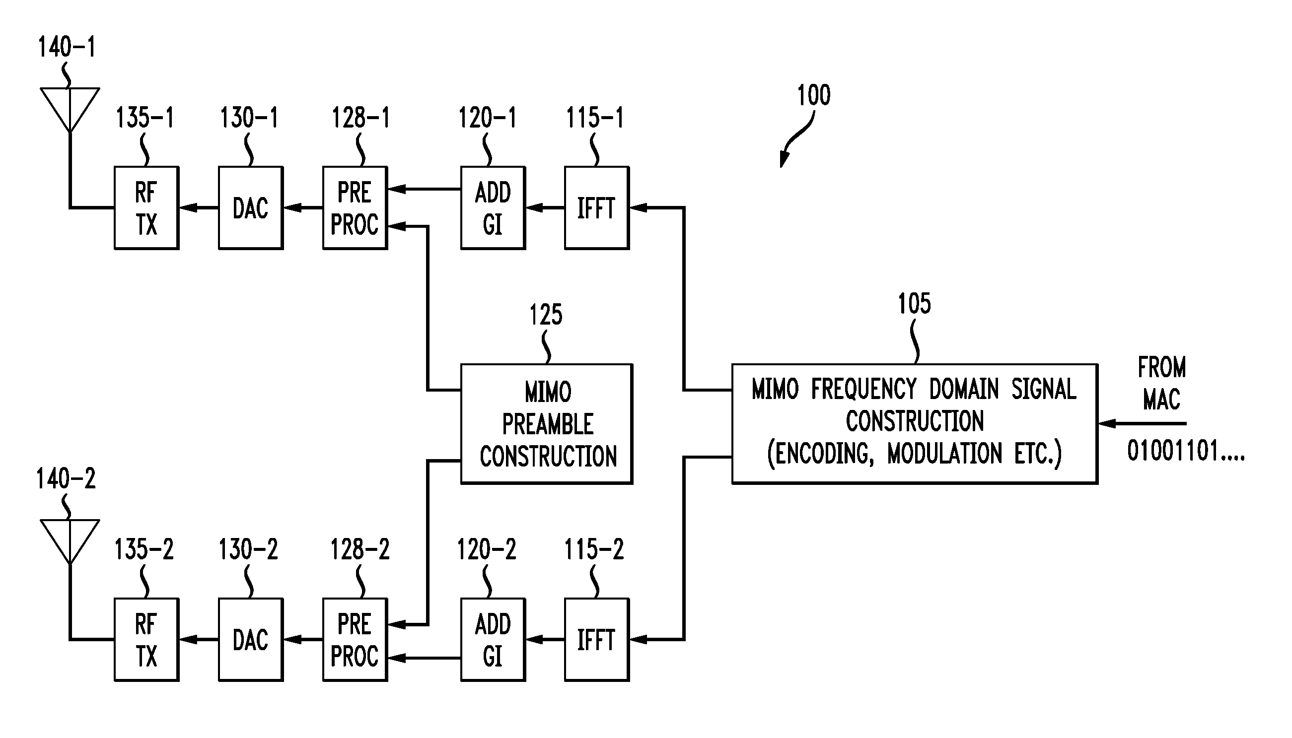
[0027] The present invention provides long and short preamble formats and techniques for preamble training for MIMO systems. FIG. 1 is a schematic block diagram of a MIMO transmitter 100. As shown in FIG. 1, the exemplary two antenna transmitter 100 encodes the information bits received from the medium access control (MAC) layer and maps the encoded bits to different frequency tones (subcarriers) at stage 105. For each transmit branch, the signal is then transformed to a time domain wave form by an IFFT (inverse fast Fourier transform) 115. A guard interval (GI) of 800 nanoseconds (ns) is added in the exemplary implementation before every OFDM symbol by stage 120 and a preamble of 32 μs is added by stage 125 to complete the packet. The digital signal is then pre-processed at stage 128 and converted to an analog signal by converter 130 before the RF stage 135 transmits the signal on a corresponding antenna 140.

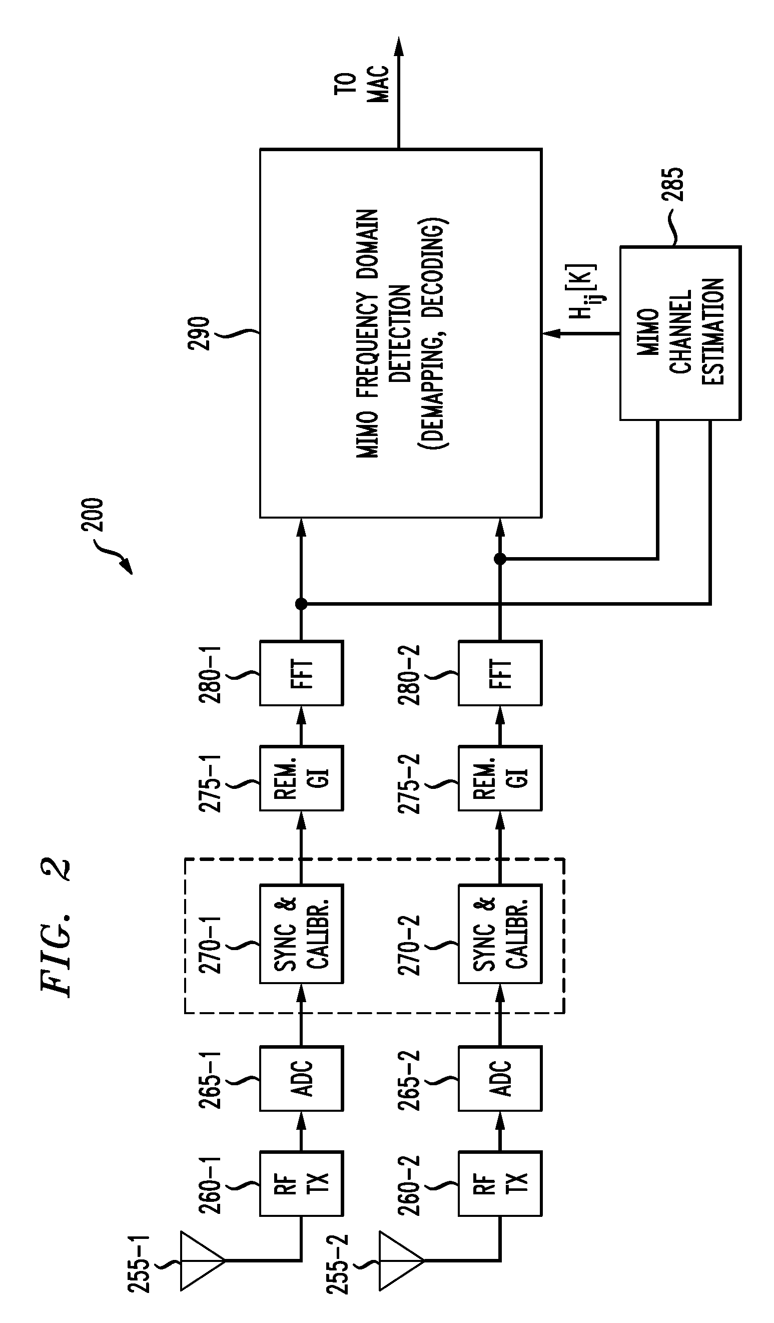
[0028]FIG. 2 is a schematic block diagram of a MIMO receiver 200. As show...


PUM


Abstract

Methods and apparatus are provided for improved long preamble formats in a multiple antenna communication system having N antennas. According to one aspect of the invention, a preamble having a legacy portion and a high throughput portion is transmitted (or received) on each of the N transmit antennas, wherein the legacy portion comprises a legacy long training field and the high throughput portion comprises at least N high throughput long training fields, wherein the N high throughput long training fields are transmitted in N time slots using an N×N orthogonal matrix. The orthogonal matrix can be, for example, one or more of a Walsh matrix and a Fourier matrix. The N time slots can optionally comprise a single symbol.

Description

CROSS-REFERENCE TO RELATED APPLICATIONS [0001] The present application claims priority to U.S. Provisional Patent Application Ser. No. 60 / 711,025, filed Aug. 23, 2005, and is related to U.S. patent application Ser. No. ______, entitled “Method and Apparatus for Reducing Power Fluctuations During Preamble Training in a Multiple Antenna Communication System Using Cyclic Delays,” and U.S. patent application Ser. No. ______, entitled “Method And Apparatus For Improved Short Preamble Formats In A Multiple Antenna Communication System,” each incorporated by reference herein.FIELD OF THE INVENTION [0002] The present invention relates generally to multiple antenna wireless communication systems, and more particularly, to preamble training techniques for a multiple antenna communication system. BACKGROUND OF THE INVENTION [0003] Multiple transmit and receive antennas have been proposed to provide both increased robustness and capacity in next generation Wireless Local Area Network (WLAN) sys...

Claims


Application Information

Patent Timeline
Patent Type & Authority Applications(United States)
IPC IPC(8): H04J11/00H04Q7/00
CPCH04B7/0669H04B7/0684H04J13/0048H04J13/18H04L27/2613
Inventor MUJTABA, SYED A.
Owner AVAGO TECH INT SALES PTE LTD
Learn More