Drive circuit for an injector arrangement
a drive circuit and injector technology, applied in the direction of electrical control, device details, electrical control, etc., can solve the problems of complex known conventional drive circuitry for controlling piezoelectric fuel injectors, requiring extensive energy, and requiring relatively high currents (tens of amps) in order to function properly, etc., to achieve the effect of small and cheaper voltage supply means, reduced size and cost of voltage supply means, and cheaper and more controllable drive circuits
- Summary
- Abstract
- Description
- Claims
- Application Information
AI Technical Summary
Benefits of technology
Problems solved by technology
Method used
Image
Examples
first embodiment
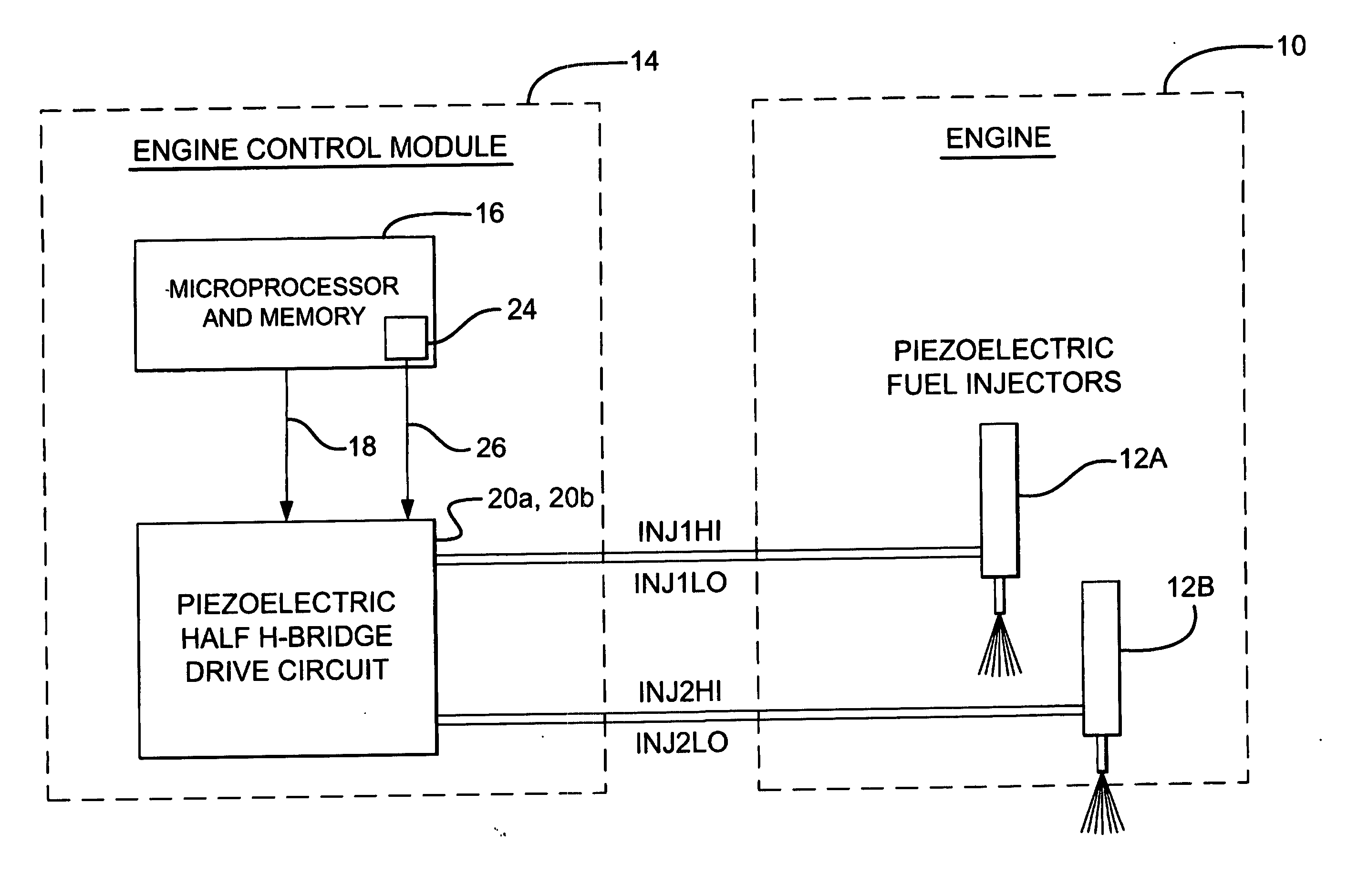
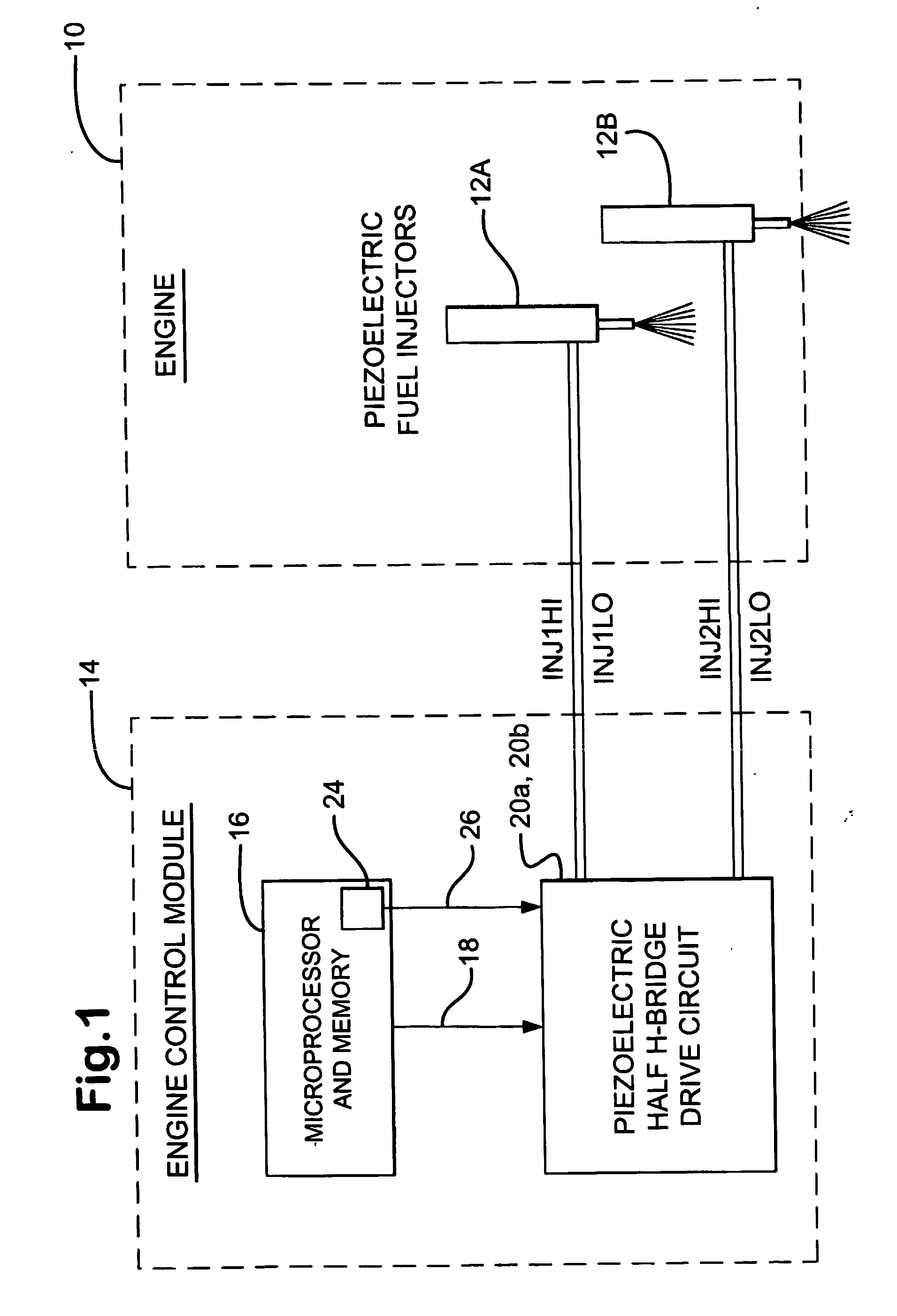
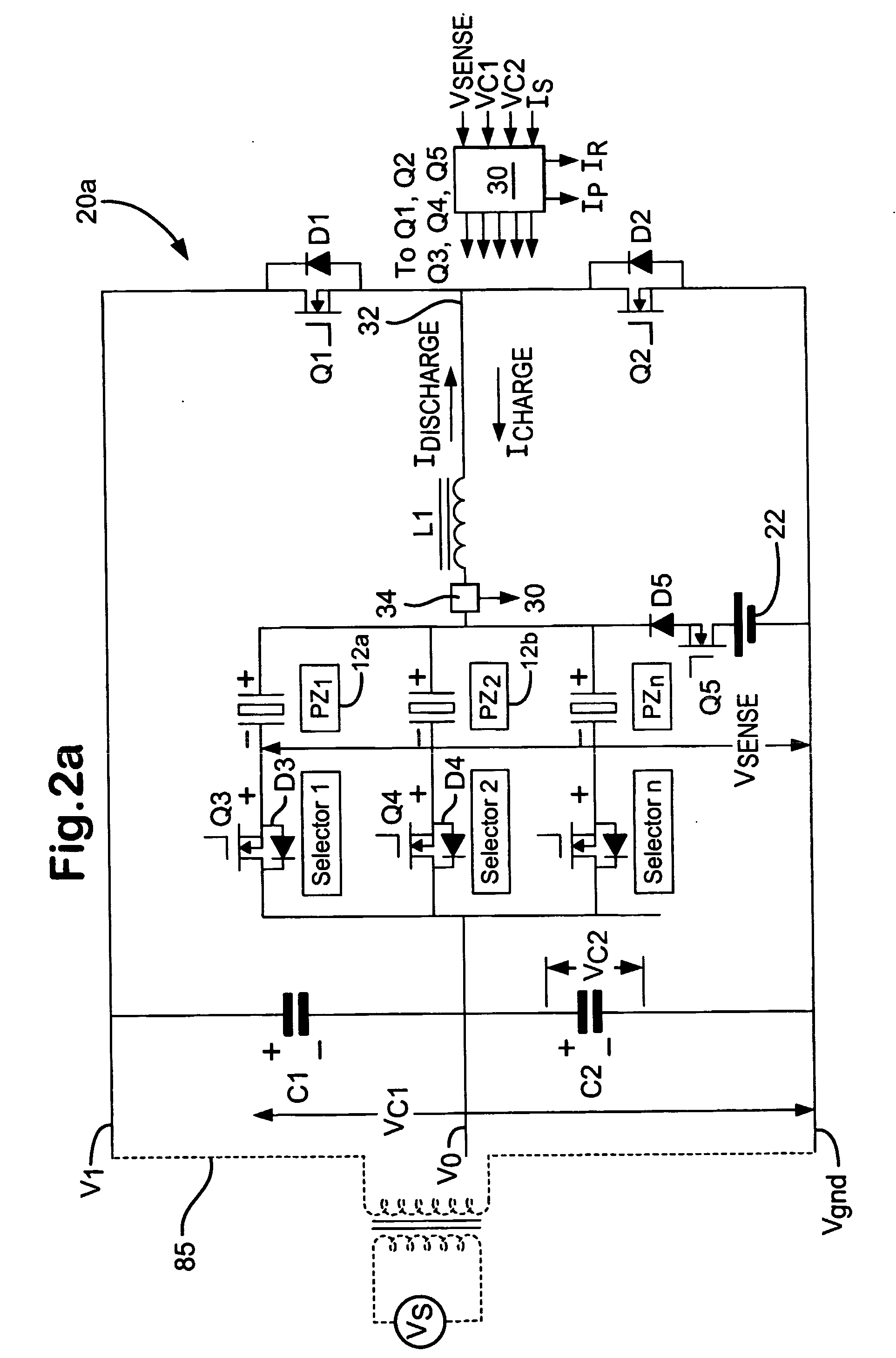
[0057] The piezoelectric drive circuit 20a, according to the present invention, is illustrated in detail in the block / circuit diagram of FIG. 2a The drive circuit 20a includes first and second voltage supply rails V0 and V1, and is generally configured as a half H-bridge having a middle circuit current path 32 which serves as a bi directional current path. The middle circuit branch 32 includes an inductor L1 coupled in series with a parallel connection of the injectors 12a and 12b and associated switching circuitry. Each injector 12a and 12b has the electrical characteristics of a capacitor, with its piezoelectric actuator stack being chargeable to hold a voltage which is the potential difference between the charge (+) and discharge (−) terminals of the injector 12a and 12b. Charging and discharging of each injector 12a,12b is achieved by controlling the flow of current through the bidirectional current path 32 by means of the microprocessor 16.
[0058] The drive circuit 20a further i...
second embodiment
[0094] Referring again to FIG. 4, with the regeneration switch Q5 activated, while the discharge switch Q2 is on, current is drawn from the vehicle battery 22 (or the PSU 36) and passes through the regeneration switch Q5, the diode D6, the inductor L1, the discharge switch Q2, and through the second energy storage capacitor C2 (as illustrated by the dashed arrows) such that the energy on the second capacitor C2 decreases. When the discharge switch Q2 is switched off, current flows from the first capacitor C1, through the regeneration switch Q5, the diode D6, the inductor L1, and the diode D1 associated with the charge switch Q1, such that the energy on the first capacitor C1 increases (shown by the bold arrows). Thus, during the regeneration phase in the invention, the inductor L1 transfers energy from the second energy storage capacitor C2 to the first energy storage capacitor C1, and the vehicle battery 22 (or the PSU 36) maintains the voltage on C2. Thus, the regeneration phase i...
PUM
 Abstract
Description
Claims
Application Information
 - R&D
- Intellectual Property
- Life Sciences
- Materials
- Tech Scout
- Unparalleled Data Quality
- Higher Quality Content
- 60% Fewer Hallucinations
Browse by: Latest US Patents, China's latest patents, Technical Efficacy Thesaurus, Application Domain, Technology Topic, Popular Technical Reports.
© 2025 PatSnap. All rights reserved.Legal|Privacy policy|Modern Slavery Act Transparency Statement|Sitemap|About US| Contact US: help@patsnap.com


