Disposable laryngeal mask airway device

a laryngeal mask and airway technology, applied in the field of laryngeal mask airway devices, can solve the problems of difficult or inability to properly insert the endotracheal tube, death of patients, and difficulty in properly inserting the tube, so as to reduce the cost of fabricating the device, improve the geometric configuration, and reduce the cost

Inactive Publication Date: 2007-05-10
INDIAN OCEAN MEDICAL INC
View PDF82 Cites 18 Cited by
  • Summary
  • Abstract
  • Description
  • Claims
  • Application Information

AI Technical Summary

Benefits of technology

[0020] These and other objects are provided by laryngeal mask airway devices that are characterized by improved geometric configurations and by methods of making such a devices. As will be discussed below, a reduced cost process for making a laryngeal mask airway device according to the invention includes a process known as rotational molding. The improved device includes two principal components: (1) a mask portion and (2) an airway tube. The device is fabricated by attaching the backplate portion of the airway tube to the mask portion. As will be discussed in greater detail below, the configuration of the two principal components (1) reduces the cost of fabricating the device and (2) improves the performance of the device.

Problems solved by technology

Although they have been enormously successful, endotracheal tubes suffer from several major disadvantages.
The principal disadvantage of the endotracheal tube relates to the difficulty of properly inserting the tube.
Also, even for skilled practitioners, insertion of an endotracheal tube is sometimes difficult or not possible.
In many instances, the difficulty of inserting endotracheal tubes has tragically led to the death of a patient because it was not possible to establish an airway in the patient with sufficient rapidity.
In addition to this principal disadvantage, there are also other disadvantages associated with endotracheal tubes.
For example, intubation with an endotracheal tube often causes patients to suffer from severe “sore throats.” The “sore throat” is principally caused by friction between the tube and the notch between the patient's arytenoid cartilages.
Another disadvantage is that patients can not cough effectively while intubated with an endotracheal tube.
Yet another problem with endotracheal tubes relates to the manner in which they are inserted.
These necessary manipulations make it difficult, or undesirable, to insert an endotracheal tube into a patient who may be suffering from a neck injury.
Still another disadvantage is that endotracheal tubes provide an airway that is relatively small or narrow.
However, one disadvantage of these materials is that they are relatively expensive.
One disadvantage of the devices disclosed in the '897 and '452 patents is that the assembly of the disclosed mask portions necessarily involves two steps: a first step of fabricating the backplate and then a second step of adhering the cuff to the top and bottom of the plate.
In addition to cost, another disadvantage of prior art laryngeal mask airway devices relates to the quality of the seal established between the patient and the device.
However, if greater pressures are applied to the proximal end of the airway tube, the seal tends to be lost thereby causing loss of some fraction of the delivered gas volume, so that positive pressure ventilation may be less effective.
Still another disadvantage of prior art laryngeal mask airway devices relates to the profile, or geometric configuration, of the deflated device.
However, prior art devices do not tend to automatically form such shapes when the cuff is deflated.
Yet another disadvantage of prior art laryngeal mask airway devices relates to the manner in which they are inserted into a patient.
Unfortunately, this procedure requires the practitioner to insert their finger into the patient's mouth and guide the device past the patient's throat.

Method used


Image

  • Disposable laryngeal mask airway device
  • Disposable laryngeal mask airway device
  • Disposable laryngeal mask airway device

Examples


Embodiment Construction

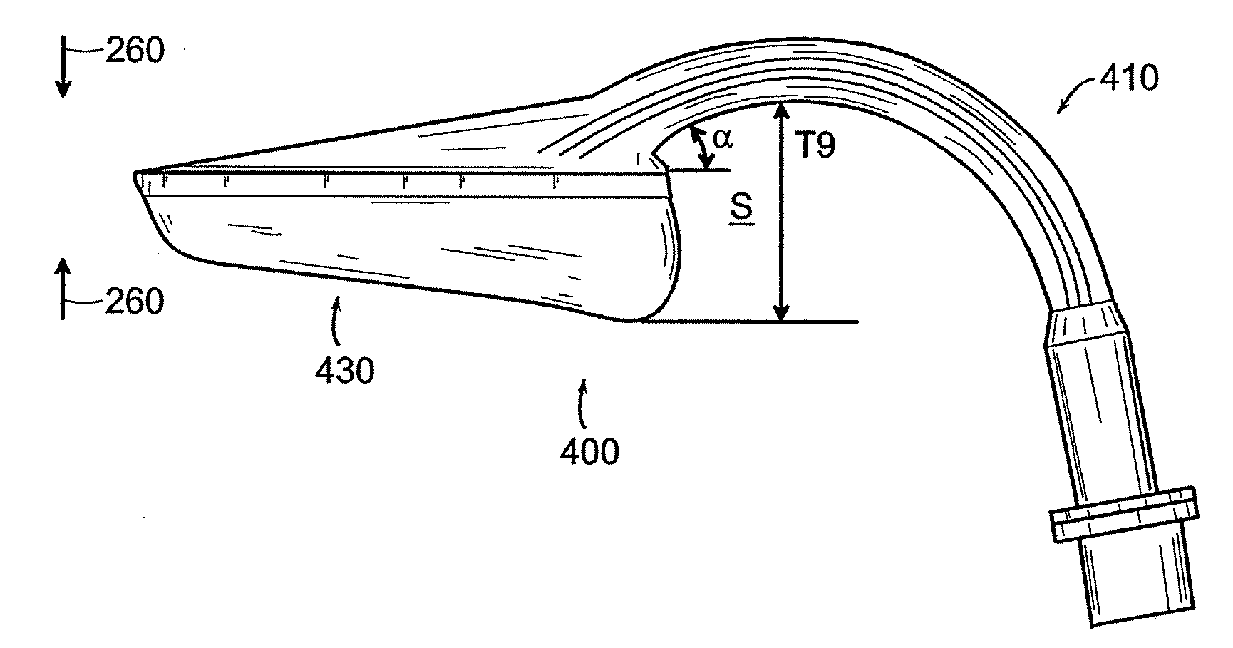
[0121]FIG. 4A shows a side view of one embodiment of a laryngeal mask airway device 400 constructed according to one aspect of the invention. FIGS. 4B and 4C show two perspective views of device 400. Device 400 is preferably constructed from two separate pieces that are bonded, or adhered, together. The first piece is an airway tube 410 and the second piece is a mask portion 430. In FIGS. 4A, 4B, and 4C, the mask portion 430 is shown in an inflated condition. As will be discussed in greater detail below, mask portion 430 may advantageously be formed by a process called rotational molding. The airway tube 410 may also be produced by rotational molding, or alternatively, could be produced using injection or other types of molding.

[0122]FIG. 5A shows a side view of mask portion 430 when inflated. FIGS. 5B and 5C show two perspective views of the anterior side of mask portion 430 when inflated. FIG. 5D shows a perspective view of the posterior side of mask portion 430 when inflated, an...


PUM


Abstract

The disclosed laryngeal mask airway device includes a mask portion and an airway tube. The mask portion includes an inflatable cuff, which defines a central opening when the cuff is inflated. The airway tube defines an internal passage extending from a proximal end of the tube to a distal end of the tube. The airway tube further defines two or more tabs disposed near the distal end of the tube. The mask portion is coupled to the airway tube near the distal end of the airway tube, and the tabs extend from the airway tube into the central opening defined by the cuff when the cuff is inflated.

Description

REFERENCE TO RELATED APPLICATIONS [0001] This application is a divisional of and claims priority under 35 U.S.C., §120 to U.S. patent application Ser. No. 10 / 138,806, filed May 3, 2002, the entire contents of which are incorporated herein by reference, and which claims priority under 35 U.S.C. § 119(e) to U.S. Provisional Patent Application No. 60 / 314,438, entitled “Disposable LMA,” which was filed Aug. 23, 2001, which is expressly incorporated herein by reference in its entirety. [0002] This application is related to U.S. patent application Ser. No. 09 / 544,681 entitled “Disposable LMA”, filed on Apr. 7, 2000 (Attorney Docket No. LMA-003, 108195-120), now U.S. Pat. No. 6,705,318, issued on Mar. 16, 2004.BACKGROUND OF THE INVENTION [0003] The present invention relates to a laryngeal mask airway device. More specifically, the present invention relates to reduced cost laryngeal masks, improved geometric configurations for laryngeal masks, and to methods of inexpensively fabricating suc...

Claims


Application Information

Patent Timeline
Patent Type & Authority Applications(United States)
IPC IPC(8): A61M16/00A61M16/04
CPCA61M16/04A61M16/0463A61M16/0488A61M2209/06A61M16/0415A61M16/0493A61M16/0409A61M16/0434A61M16/0443A61M16/0445
Inventor BRAIN, ARCHIBALD I. J.
Owner INDIAN OCEAN MEDICAL INC
Why Eureka
Try Eureka