
Profiled insulation LAN cables

a technology of cable and insulation, applied in the field of insulation in cables, can solve the problems of insertion loss of signals propagated along the cables, several limitations of the foaming process, and no chemical foaming is used

Active Publication Date: 2007-05-03
BERK TEK
View PDF9 Cites 27 Cited by
  • Summary
  • Abstract
  • Description
  • Claims
  • Application Information

AI Technical Summary

Benefits of technology

[0012] It is another object of the present invention to provide a profiled insulation having a central opening and an outer circumference having a thickness, with at least one longitudinal cavity therein, the longitudinal cavity is substantially between 0.0025″ and 0.0004.″

Problems solved by technology

Although these insulations provide good flame resistant properties needed to meet fire safety standards, such as UL riser and UL plenum ratings, they have relatively high dielectric constants, tending to cause insertion loss in the signals propagated along the cables.
However, there are several limitations with the foaming process.
This process requires additional equipment such as a gas pressurization unit to inject the gas at a critical velocity into the polymer and complex screw designs such as multi-stage screws and an extrusion barrel with gas injection ports.
However, chemical foaming is not used as frequently as physical foaming because this method also has negative drawbacks inherent in the process.
Chemical foam and gas injection extrusion lines are difficult to control and run slowly with low yields.
However, prior art attempts in this area are unsatisfactory, particularly with respect to insulation for each individual conductor in a twisted pair.
However, such a technique is not equally applicable to placing an insulator in an individual conductor from a twisted pair which is significantly smaller in diameter.
Further disadvantages of the '155 patent methodology include the fact that the extrusion die used is a complicated multi-component die, requiring significant upkeep.
Also, there is no ability to adjust the pressure within the cavities during extrusion without shutdown and re-tooling.
Thus, the prior art does not exhibit any means for both reducing the dielectric constant of the insulation, such as insulation on the individual copper conductors of a twisted pair communication cable, without the costly addition of materials need to foam the insulation.

Method used


Image

  • Profiled insulation LAN cables
  • Profiled insulation LAN cables
  • Profiled insulation LAN cables

Examples


Embodiment Construction

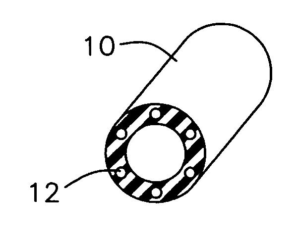
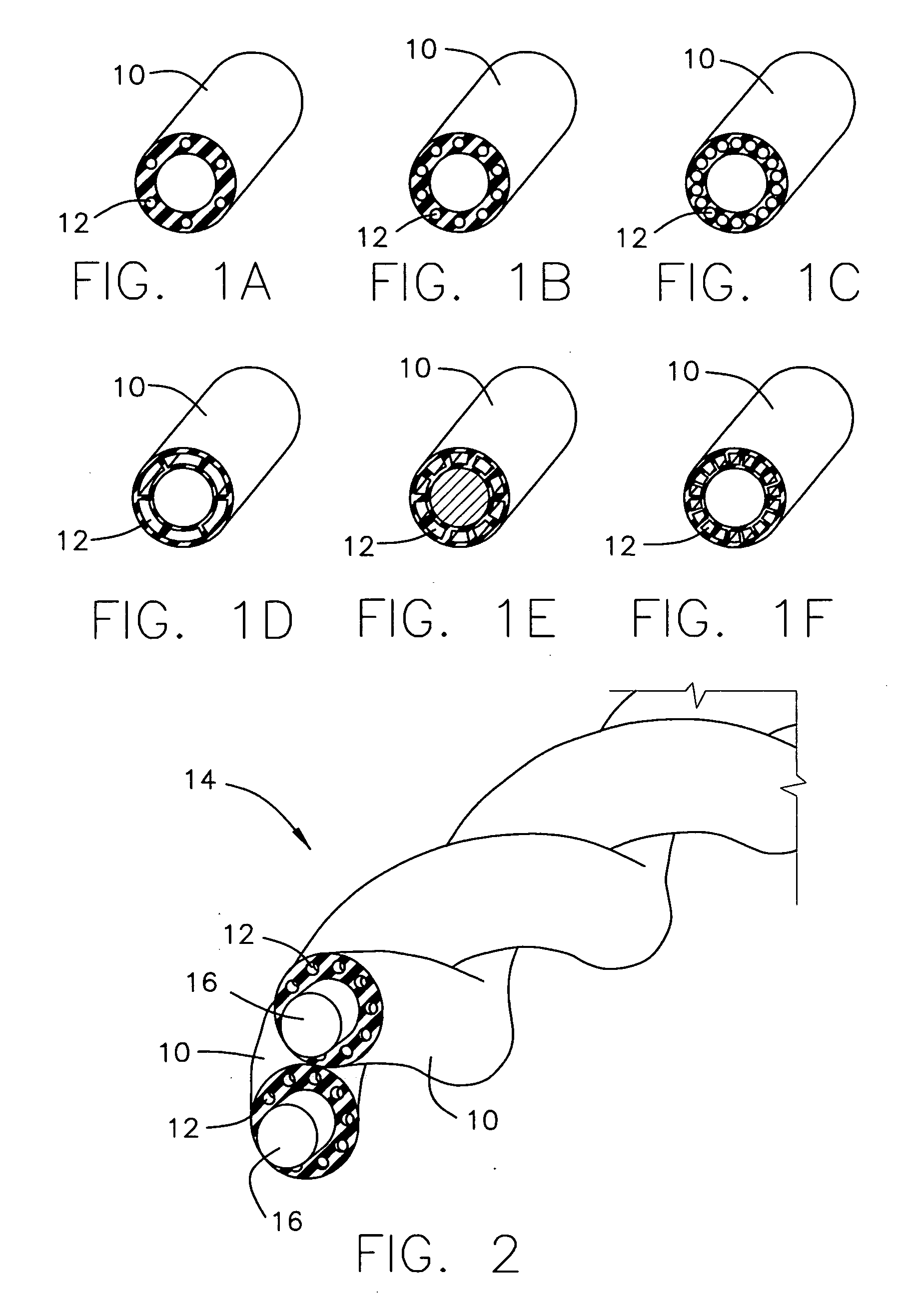
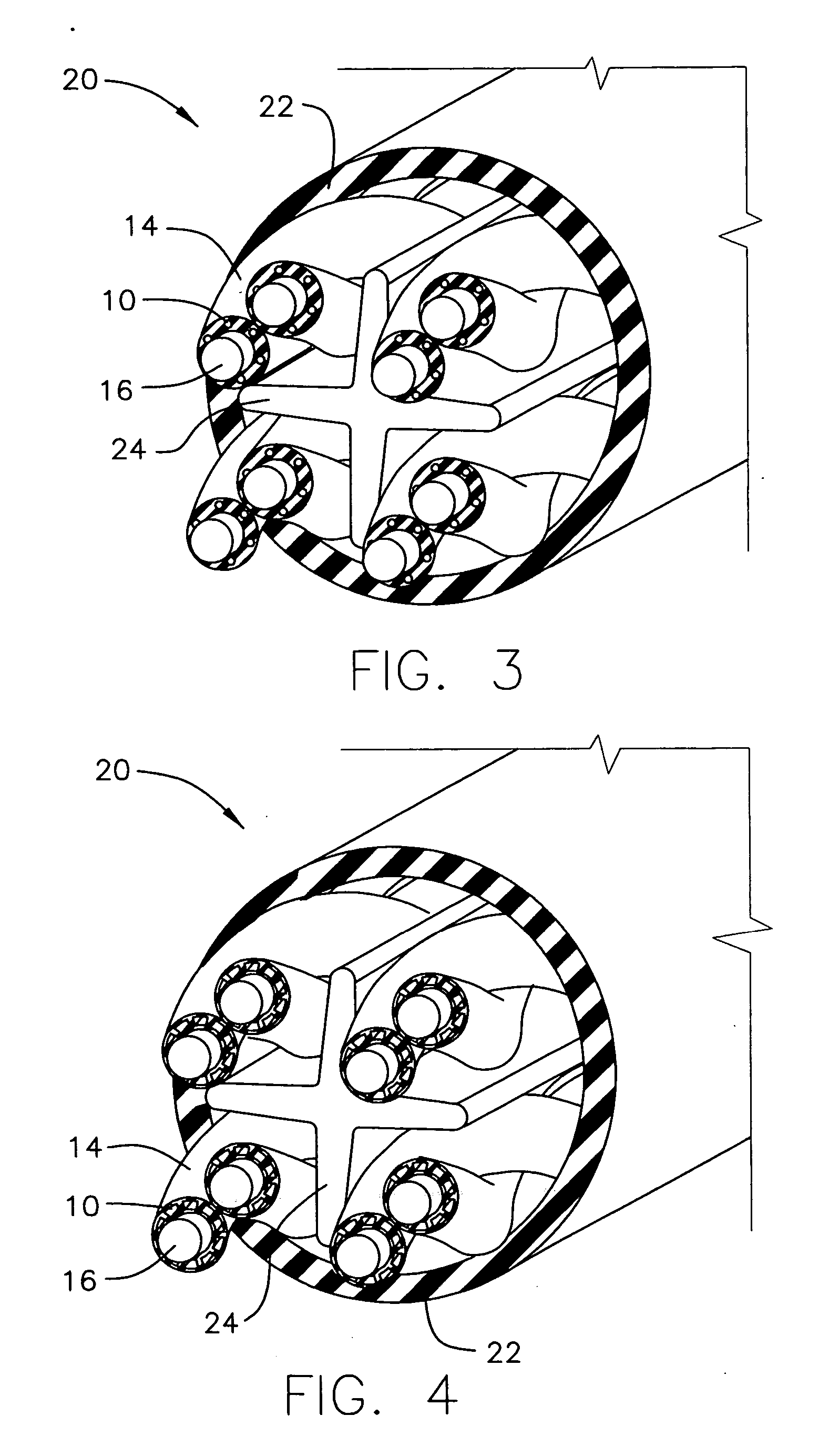
[0023] In one embodiment of the present invention, as illustrated in FIGS. 1A through 1F, a profiled insulation 10 is provided. Profiled insulation generally refers to an insulator, typically for use on a conductor from a twisted pair. Unlike common solid (usually cylindrical) polymer insulation, profiled insulation 10 of the present invention has additional physical characteristics regarding its shape as discussed below.

[0024] Profiled insulation 10 is preferably constructed from a thermoplastic polymer insulation (dielectric), such as FEP (Fluorinated Ethylene-Propylene), however, any suitable polymer may be used according to any one of the desired insulation capabilities, fire resistance properties, mechanical strengths or the desired production rates of profiled insulation 10.

[0025] Each profiled insulation 10 is provided with one or more cavities 12 that extend along the longitudinal axis of insulation 10. Cavities 12 are disposed within the insulation itself and may have a c...


PUM

PropertyMeasurementUnit
Pressureaaaaaaaaaa
Volumetric flow rateaaaaaaaaaa

Abstract

A device for making a profiled insulation having an extrusion die with an extrusion tip and a polymer chamber surrounding the extrusion tip. The polymer chamber has at least one air chamber therein. The air chamber is held in place and coupled to the outside of the extrusion die by a vertical fin extending outwards from the extrusion tip. When molten polymer flows through the polymer chamber around the air chamber, an opening is introduced into the polymer such that the profiled insulation is formed as the polymer exits the extrusion die, having a longitudinal cavity therein corresponding to the location of the opening formed by the at least one air chamber.

Description

FIELD OF THE INVENTION [0001] The present invention relates to insulation in cables such as LAN (Local Area Network) cables. More particularly the present invention relates to profiled insulation in cables, having a reduced effective dielectric. BACKGROUND OF THE INVENTION [0002] In the field of cables, such as LAN cables, certain common insulators are used for forming the twisted pair insulation as well as the outer jacket. Common polymers used include FEP (Fluorinated Ethylene Propylene) and PE (Polyethylene). Although these insulations provide good flame resistant properties needed to meet fire safety standards, such as UL riser and UL plenum ratings, they have relatively high dielectric constants, tending to cause insertion loss in the signals propagated along the cables. [0003] One approach in the prior art for reducing the dielectric constant of an insulator is to introduce air or gas into the polymer insulation during the extrusion process in order to foam the insulation. Typ...

Claims


Application Information

Patent Timeline
IPC IPC(8): B32B1/08B29C47/58B29C48/50
CPCY10T428/139H01B13/14H01B7/0233H01B11/002H01B19/00H01B17/00
Inventor HEFFNER, GREG
Owner BERK TEK
Learn More