Fluid pump having a simplified structure
a technology of fluid pump and simplified structure, which is applied in the direction of pump components, positive displacement liquid engines, rotary piston liquid engines, etc., can solve the problems of fluid pump damage, heat dissipation model, and object damage, and achieve the effect of avoiding fluid leakag
- Summary
- Abstract
- Description
- Claims
- Application Information
AI Technical Summary
Benefits of technology
Problems solved by technology
Method used
Image
Examples
first embodiment
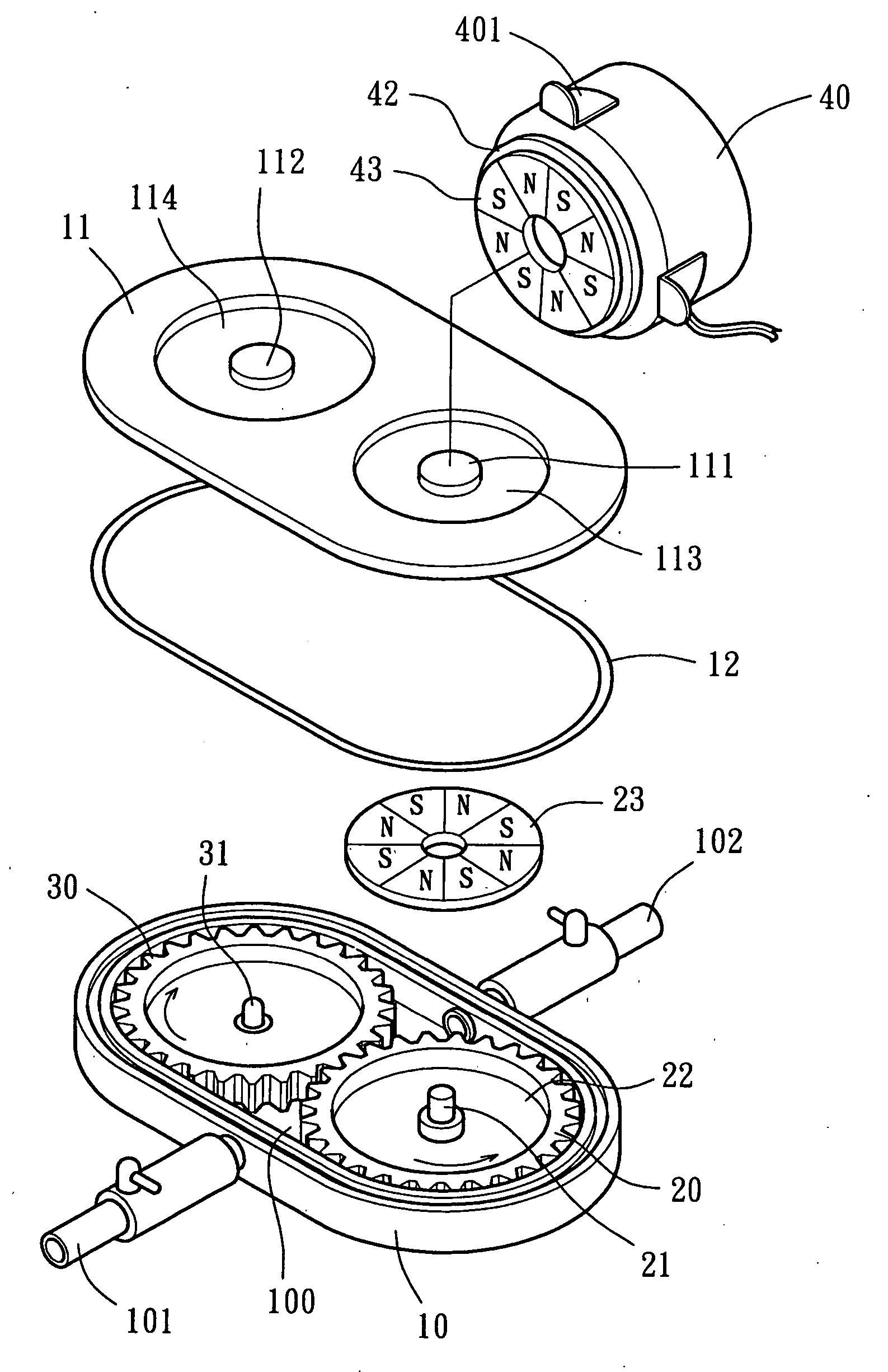
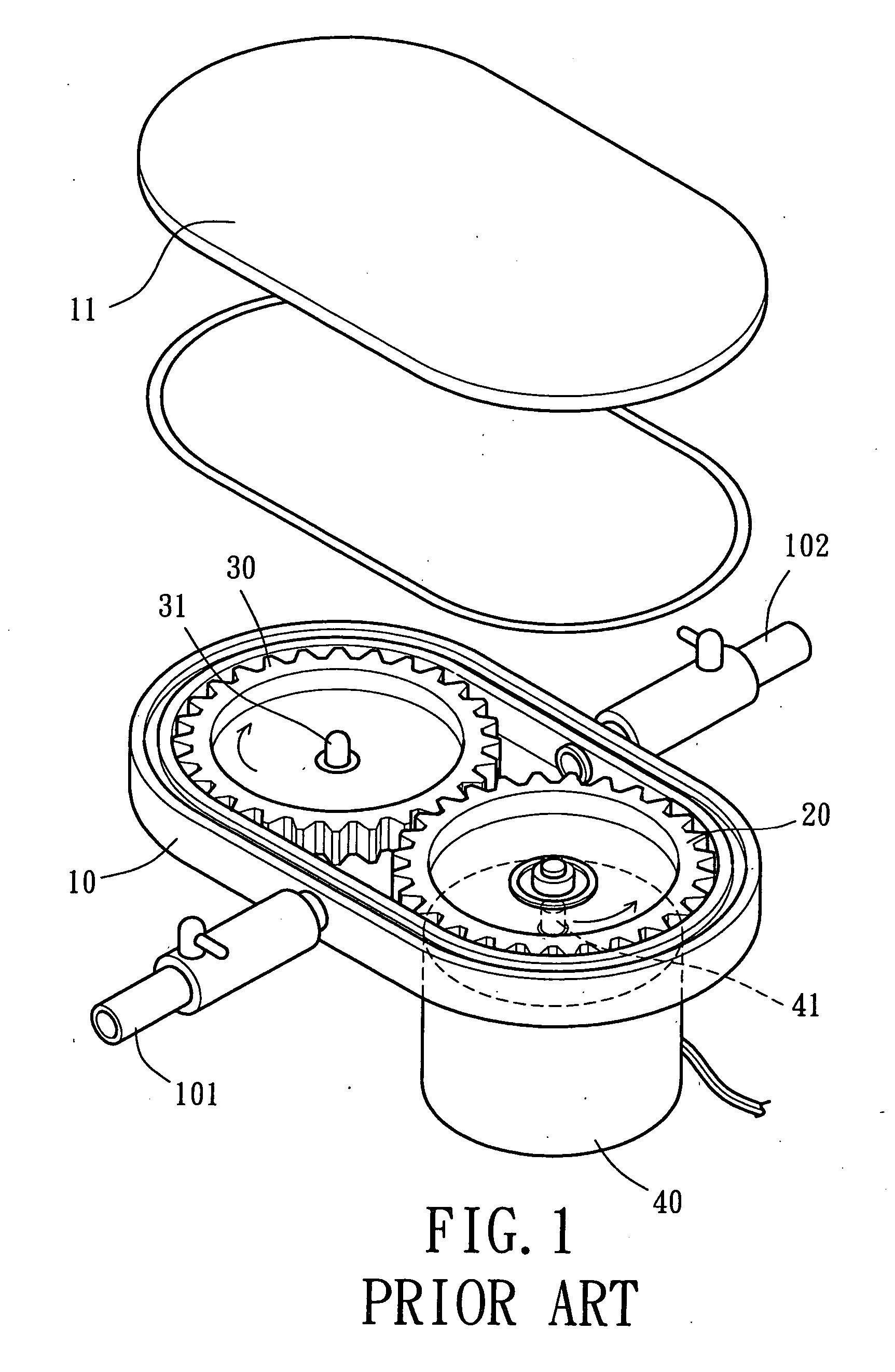
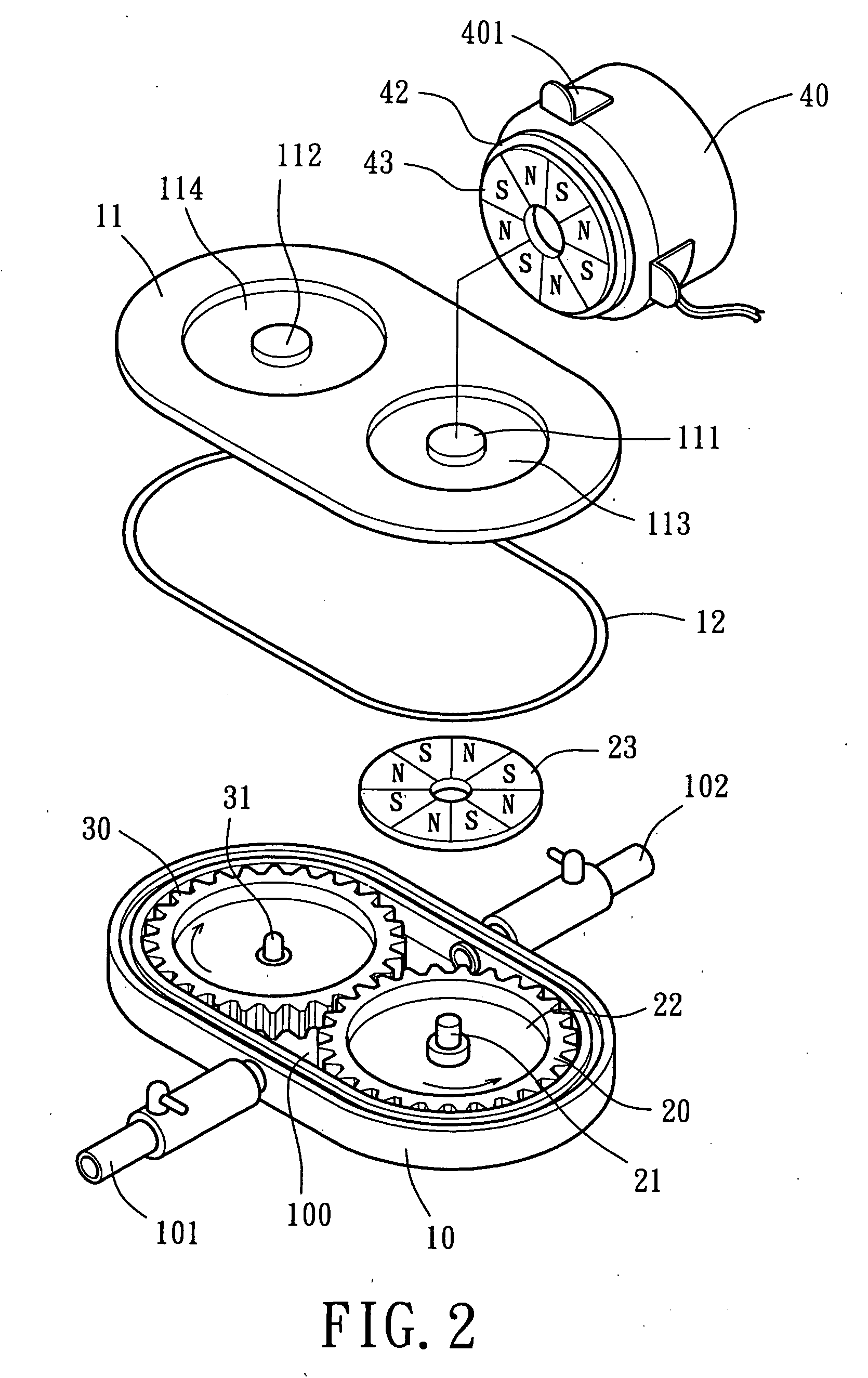
[0038] Referring to FIG. 2, a fluid pump in accordance with the present invention comprises a housing 10, at least one drive gear 20, at least one driven gear 30, and a driving member 40. The fluid pump may drive a fluid to flow. For example, the fluid pump can be coupled with a fluid-cooling type heat-dissipating module (not shown) and drive a fluid to flow in a circulating way for dissipating an object (such as a central processing chip of a computer). The fluid pump can be used in other fluid mechanisms and operated in a similar way.
[0039] Referring to FIGS. 2 and 3, housing 10 is of an appropriate shape such as elliptic. The housing 10 includes an interior space 100, a first shaft seat 103, and a second shaft seat 104. A lid 11 and a washer (or gasket) 12 are mounted to cover and seal the housing 10. The drive gear 20 and the driven gear 30 are mounted in the interior space 100. An inlet pipe 101 and an outlet pipe 102 are mounted to opposite sides of the housing 10 at locations...
second embodiment
[0050]FIGS. 4 and 5 illustrate the fluid pump in accordance with the present invention, wherein the second magnetically inductive member 43 of the driving member 40 is eccentric to the first magnetically inductive member 23 of the drive gear 20. In a case that both of the first magnetically inductive member 23 and the second magnetically inductive member 43 are magnets, the number of the north pole sections N and south pole sections S of the first magnetically inductive member 23 may be different from that of the north pole sections N and south pole sections S of the second magnetically inductive member 43. Further, the drive gear 20 and the driven gear 30 may differ in size and in the number of teeth. For example, the size of the driven gear 30 may be larger than that of the drive gear 20 and the number of the teeth of the driven gear 30 may be greater than that of the drive gear 20, and vice versa. The number of the drive gear 20 and the driven gear 30 may vary according to need.
[...
third embodiment
[0052]FIGS. 6 and 7 illustrate the fluid pump in accordance with the present invention, wherein the second magnetically inductive member 43 of the driving member 40 is a magnet with a plurality of north pole sections N and a plurality of south pole sections S whereas the first magnetically inductive member 23 of the drive gear 20 is a magnetically conductive plate such as an iron plate. The size of the first magnetically inductive member 23 is apparently smaller than that of the second magnetically inductive member 43 and preferably equal to or smaller than that of the north pole sections N and the south pole sections S of the second magnetically inductive member 43. The drive gear 20 is turned by the driving member 40 through use of the first and second magnetically inductive members 23 and 43. The interior space 100 of the housing 10 is designed to receive only the drive gear 20, as the driven gear 30 is omitted. The structure of the fluid pump is thus simplified. Rotation of the ...
PUM
 Abstract
Description
Claims
Application Information
 - R&D
- Intellectual Property
- Life Sciences
- Materials
- Tech Scout
- Unparalleled Data Quality
- Higher Quality Content
- 60% Fewer Hallucinations
Browse by: Latest US Patents, China's latest patents, Technical Efficacy Thesaurus, Application Domain, Technology Topic, Popular Technical Reports.
© 2025 PatSnap. All rights reserved.Legal|Privacy policy|Modern Slavery Act Transparency Statement|Sitemap|About US| Contact US: help@patsnap.com


