Milling head for removing heat dissipating elements from a tube

a technology of heat dissipation elements and milling heads, which is applied in the direction of shaping cutters, manufacturing tools, portable lathes, etc., can solve the problems that the tubes sometimes need replacement, and achieve the effect of efficient tube preparation

Active Publication Date: 2007-05-03
CLIMAX PORTABLE MACHINE TOOLS
View PDF43 Cites 29 Cited by
  • Summary
  • Abstract
  • Description
  • Claims
  • Application Information

AI Technical Summary

Benefits of technology

[0012] In a further embodiment, a milling head is provided that allows for precision milling of the tube end and is capable of performing multiple operations simultaneously to enable a user to efficiently complete tube preparation.

Problems solved by technology

On account of deterioration due to corrosion and the like, tubes occasionally require replacement.

Method used


Image

  • Milling head for removing heat dissipating elements from a tube
  • Milling head for removing heat dissipating elements from a tube
  • Milling head for removing heat dissipating elements from a tube

Examples


Embodiment Construction

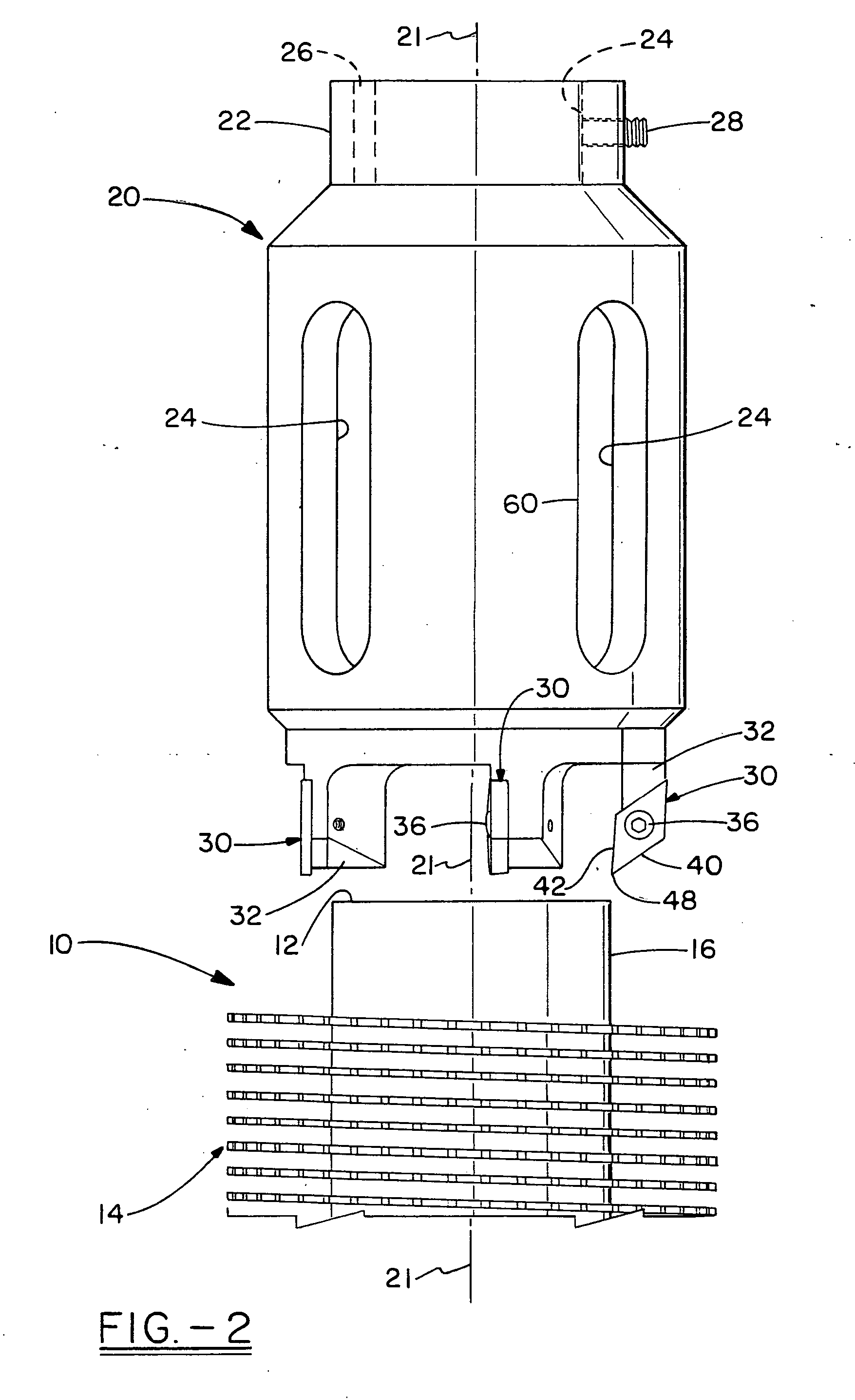
[0024] This description of preferred embodiments is to be read in connection with the accompanying drawings, which are part of the entire written description of this invention. In the description, corresponding reference numbers are used throughout to identify the same or functionally similar elements. Relative terms such as “horizontal,”“vertical,”“up,”“down,”“top” and “bottom” as well as derivatives thereof (e.g., “horizontally,”“downwardly,”“upwardly,” etc.) should be construed to refer to the orientation as then described or as shown in the drawing figure under discussion. These relative terms are for convenience of description and are not intended to require a particular orientation unless specifically stated as such. Terms including “inwardly” versus “outwardly,”“longitudinal” versus “lateral” and the like are to be interpreted relative to one another or relative to an axis of elongation, or an axis or center of rotation, as appropriate. Terms concerning attachments, coupling ...


PUM

PropertyMeasurementUnit
angleaaaaaaaaaa
angleaaaaaaaaaa
angleaaaaaaaaaa

Abstract

A milling head for a milling device, particularly a rotary milling device, wherein the milling head is capable of imparting a desired finish on a tube, preferably of a heat exchanger tube. The milling head includes one or more milling elements capable of cutting and/or removing heat dissipating elements connected to an outer surface of the tube. The heat dissipating elements are removed from the tube in a longitudinal direction along the tube length. In one embodiment, the milling head also includes a bevel milling element. Methods for milling a tube having heat dissipating elements are also described.

Description

FIELD OF THE INVENTION [0001] The present invention relates to a milling head for a milling device, particularly a rotary milling device, wherein the milling head is capable of imparting a desired finish on a tube, preferably of a heat exchanger tube. The milling head includes one or more milling elements capable of cutting and / or removing heat dissipating projections or elements connected to an outer cylindrical surface of the tube. The heat dissipating elements are removed from the tube in a longitudinal direction along the tube length. In one embodiment, the milling head also includes a bevel milling element. Methods for milling a tube having heat dissipating elements are also described. BACKGROUND OF THE INVENTION [0002] Power generating or other plants circulate fluids, such as water or steam, through tubes or banks of tubes. The fluid is often heated and used, for example, to drive turbines which generate electricity. On account of deterioration due to corrosion and the like, ...

Claims


Application Information

Patent Timeline
Patent Type & Authority Applications(United States)
IPC IPC(8): B23C3/00
CPCB23B5/167Y10T29/49995B23B2260/004B23C5/22B23P6/00B23P15/26Y10T409/30532Y10T82/22Y10T409/309408Y10T29/49726Y10T409/304144Y10T407/1924Y10T29/5199Y10T409/305208Y10T409/307168Y10T408/893Y10T29/5168Y10T407/1936Y10T29/49352Y10T409/303808Y10T408/909B23B2210/02
Inventor HALL, J. RANDALL
Owner CLIMAX PORTABLE MACHINE TOOLS
Why Eureka
Try Eureka