X-ray detector and x-ray ct apparatus
a detector and x-ray technology, applied in the field of x-ray detectors and x-ray ct apparatuses, can solve the problems of difficult to reduce the size of gaps, deterioration of the efficiency of x-ray utilization of solid-state detectors, etc., and achieve the effect of reducing the insensitive region, improving the efficiency of x-ray utilization, and reducing the size of gaps
- Summary
- Abstract
- Description
- Claims
- Application Information
AI Technical Summary
Benefits of technology
Problems solved by technology
Method used
Image
Examples
first embodiment
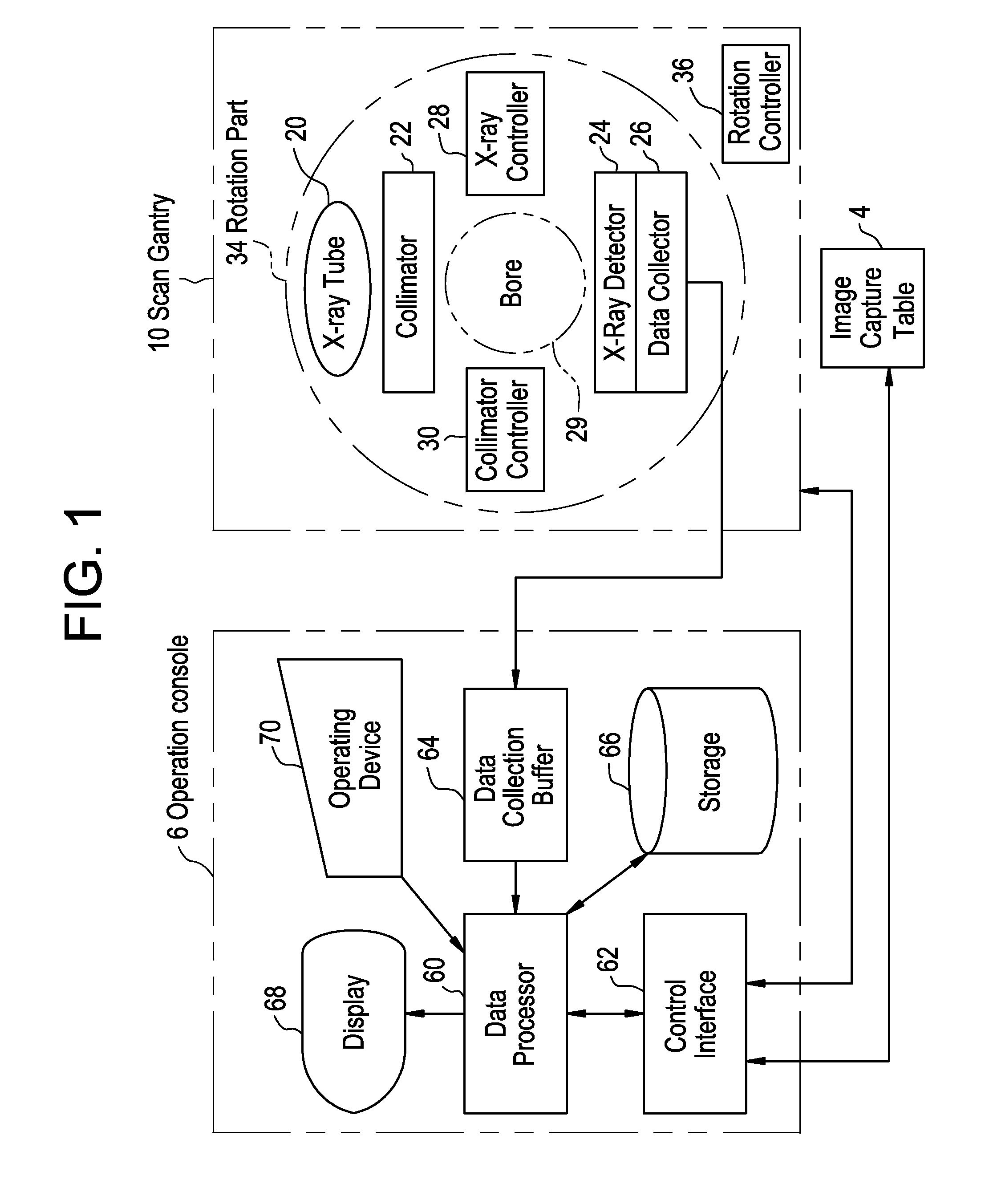
[0061] A general configuration of an X-ray CT apparatus according to a first embodiment will be described. FIG. 1 is a block diagram of an X-ray CT apparatus. As shown in FIG. 1, the apparatus has a scan gantry 10 and an operation console 6.
[0062] The scan gantry 10 has an X-ray tube 20. A not-shown X-ray emitted from the X-ray tube 20 spreads, for example, in a fan shape having a thickness and is shaped into a conical X-ray beam by a collimator 22 and is emitted to an X-ray detector 24.
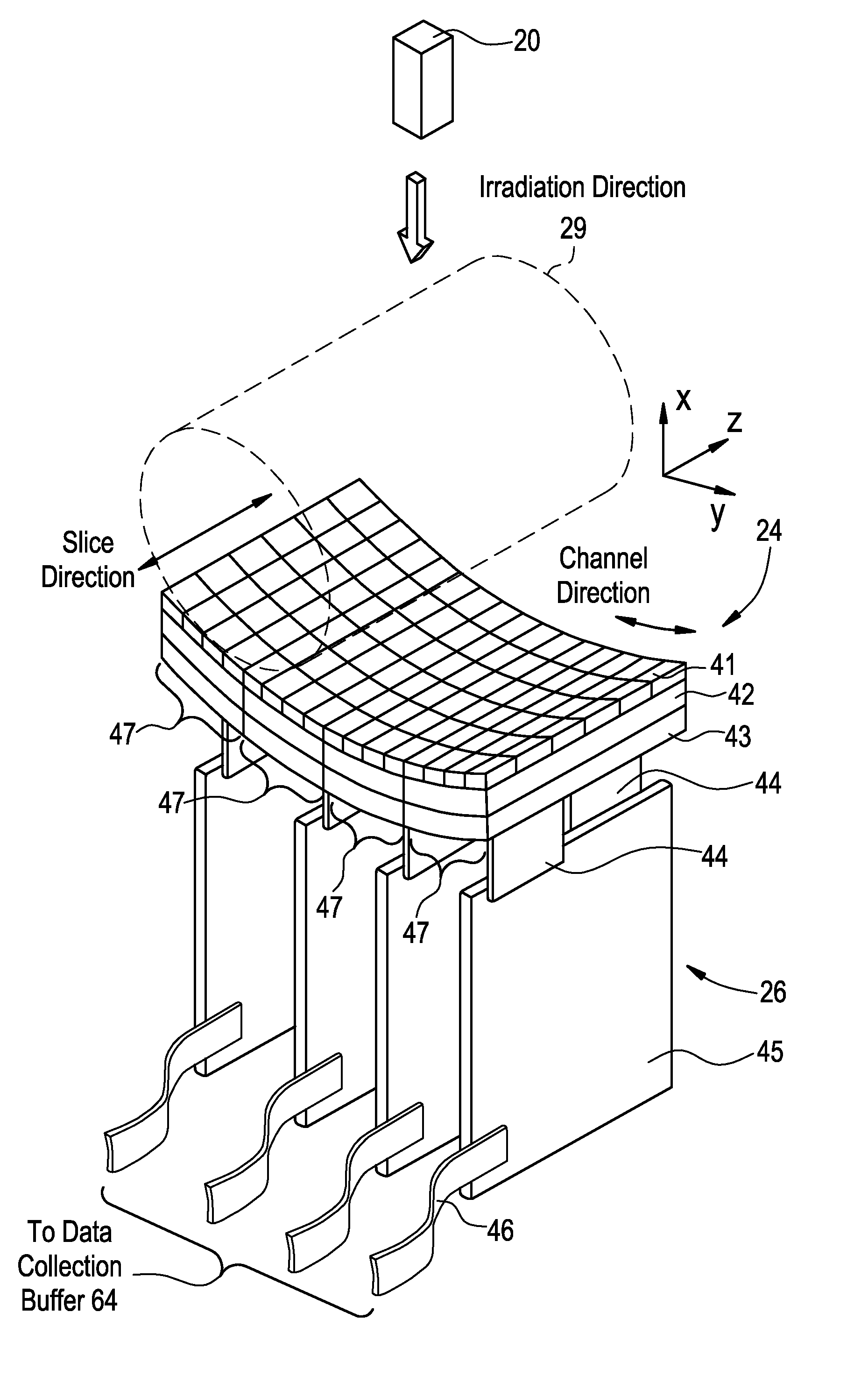
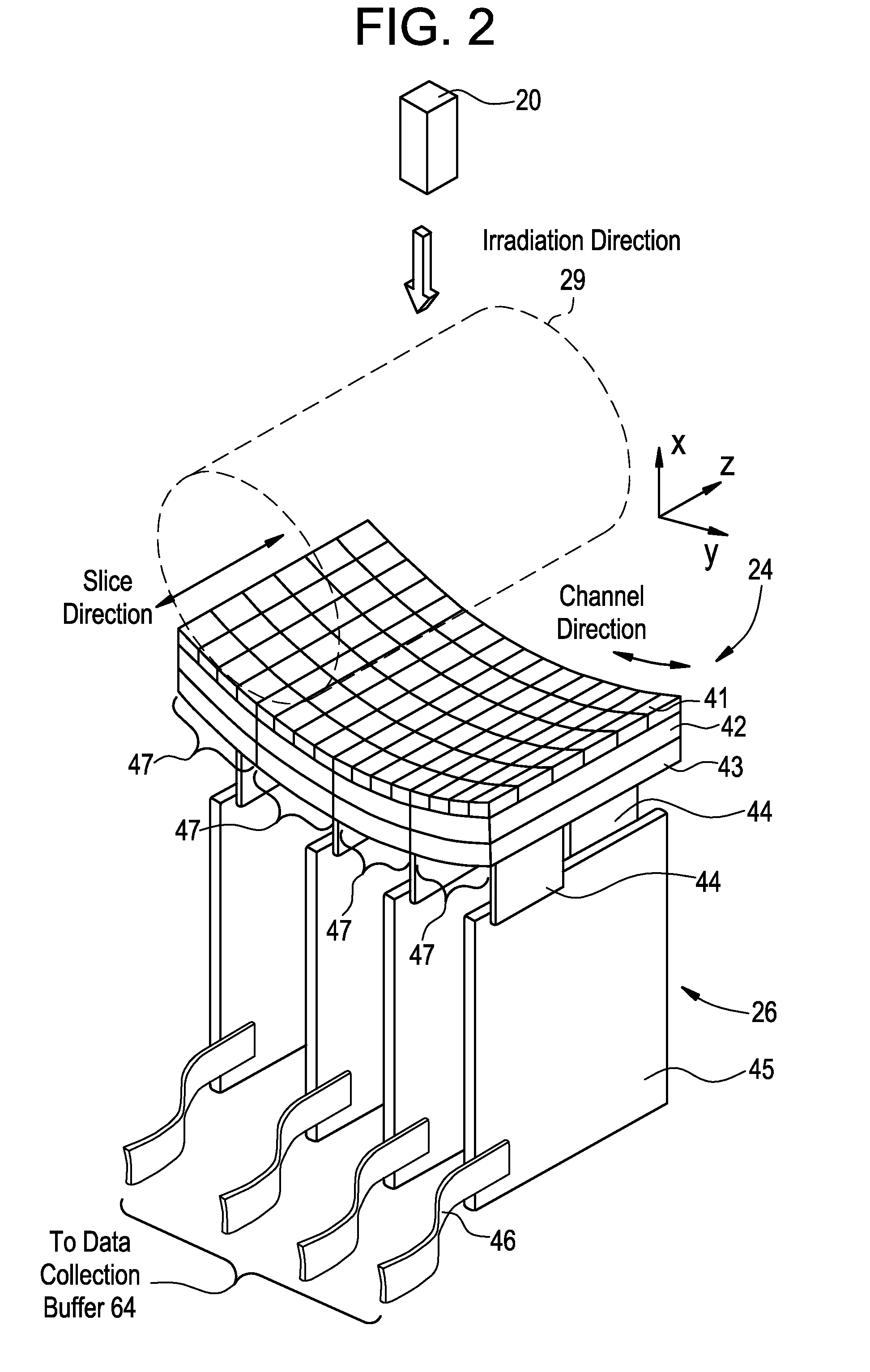
[0063] The X-ray detector 24 has a plurality of scintillators arranged in a matrix in the spread direction of the fan-shaped X-ray beam. The X-ray detector 24 is a multi-channel detector having a width in which a plurality of scintillators are arranged two-dimensionally in a matrix in the channel direction and the slice direction.
[0064] In the X-ray detector 24, an X-ray incident surface curved in a concave shape as a whole is formed. The X-ray detector 24 is obtained by combining, for example, sc...
second embodiment
[0093] In the foregoing first embodiment, the scintillator 41 has a parallelepiped structure in which the top face “a” and the under face “c” are deviated from each other only by the amounts exceeding the width of the gap 50, thereby eliminating X-ray insensitive areas when viewed from the X-ray incidence direction, typified by the gaps 50. Alternately, by forming the scintillator in a rectangular parallelepiped structure and tilting the plane block on which the scintillators are mounted with respect to the incident X-ray, X-ray insensitive areas when viewed from the X-ray incidence direction can be eliminated. In a second embodiment, the case where the scintillator has a rectangular parallelepiped structure and the plane block is tilted with respect to the incident X-ray will be described. Since the general configuration of the invention according to the second embodiment is the same as that shown in FIG. 1, its detailed description will not be repeated here.
[0094]FIGS. 6A and 6B ...
third embodiment
[0103] In the first embodiment, the scintillator 41 has a parallelepiped structure in which the top face “a” and an under face “c” are deviated from each other by an amount exceeding the width of the gap 50, thereby eliminating the X-ray insensitive area when viewed from the X-ray incidence direction. Alternately, by using a multilayer scintillator as a multilayer solid state detector in which a plurality of scintillators each having a rectangular parallelepiped structure are stacked, similarly, an X-ray insensitive area of a two-dimensional scintillator array can be eliminated when viewed from the X-ray incidence direction. In the third embodiment, a multilayer scintillator in which a number of scintillators each having a rectangular parallelepiped structure are stacked will be disclosed. Since a general configuration of the invention according to the third embodiment is the same as that shown in FIG. 1, its detailed description will not be repeated.
[0104]FIG. 8A is a cross sectio...
PUM
| Property | Measurement | Unit |
|---|---|---|
| width | aaaaa | aaaaa |
| shape | aaaaa | aaaaa |
| width | aaaaa | aaaaa |
Abstract
Description
Claims
Application Information
 - R&D
- Intellectual Property
- Life Sciences
- Materials
- Tech Scout
- Unparalleled Data Quality
- Higher Quality Content
- 60% Fewer Hallucinations
Browse by: Latest US Patents, China's latest patents, Technical Efficacy Thesaurus, Application Domain, Technology Topic, Popular Technical Reports.
© 2025 PatSnap. All rights reserved.Legal|Privacy policy|Modern Slavery Act Transparency Statement|Sitemap|About US| Contact US: help@patsnap.com


