
Lighting device

a technology of light source and laser, which is applied in the field of lamps, can solve the problems that plasma balls and lava lamps cannot effectively attract people's attention, and require expensive peripheral devices to drive lasers

Inactive Publication Date: 2007-05-03
CHICH ROBERT H
View PDF5 Cites 106 Cited by
  • Summary
  • Abstract
  • Description
  • Claims
  • Application Information

AI Technical Summary

Benefits of technology

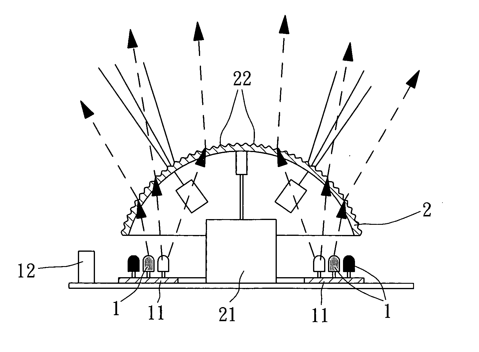
[0008] In one embodiment of the present invention, the driving device is adapted to rotate the lens relative to the light source. In another embodiment of the present invention, the driving mechanism is adapted to rotate the light source relative to the lens. Further, the raised portions of the lens may be made in different sizes and shapes, and arranged in an array or irregularly distributed over the surface of the lens. The lens can also have many different geometric shapes as well as being a flat shape with raised portions for refracting the light depending on the shape of the enclosure and the lighting effect that is being produced. And the programmable controller can also control the rotation of the driving device causing it to start and stop periodically depending on how the lighting effect has been programmed.

Problems solved by technology

Further, when a laser light source is used to produce images of laser light, expensive peripheral apparatus (such as stepper motors and computer control systems) are needed to drive the laser light source.
However, due to monotonous lighting effects and a long presence in market, these plasma balls and LAVA lamps cannot effectively attract people's attention.

Method used


Image

  • Lighting device
  • Lighting device
  • Lighting device

Examples


Embodiment Construction

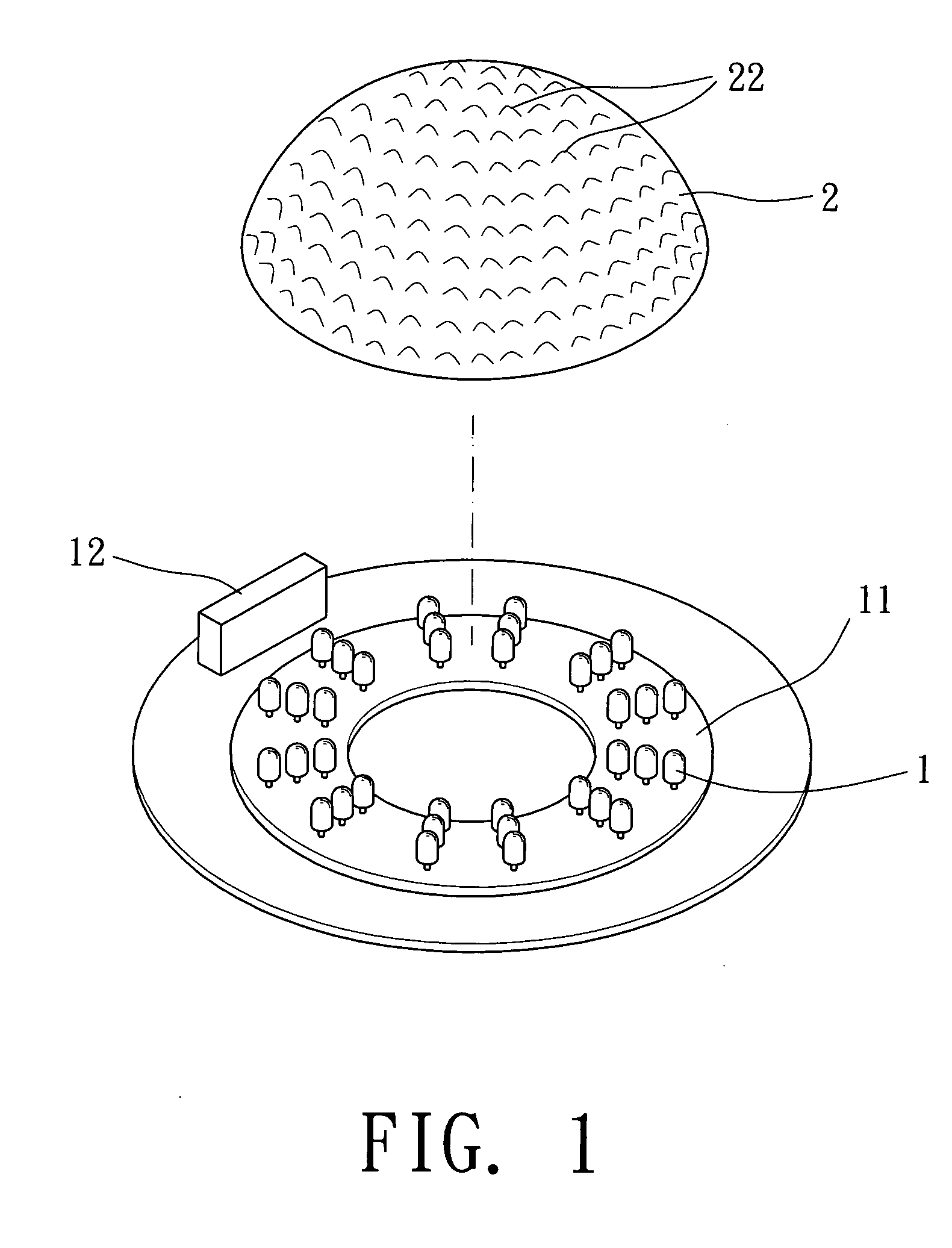
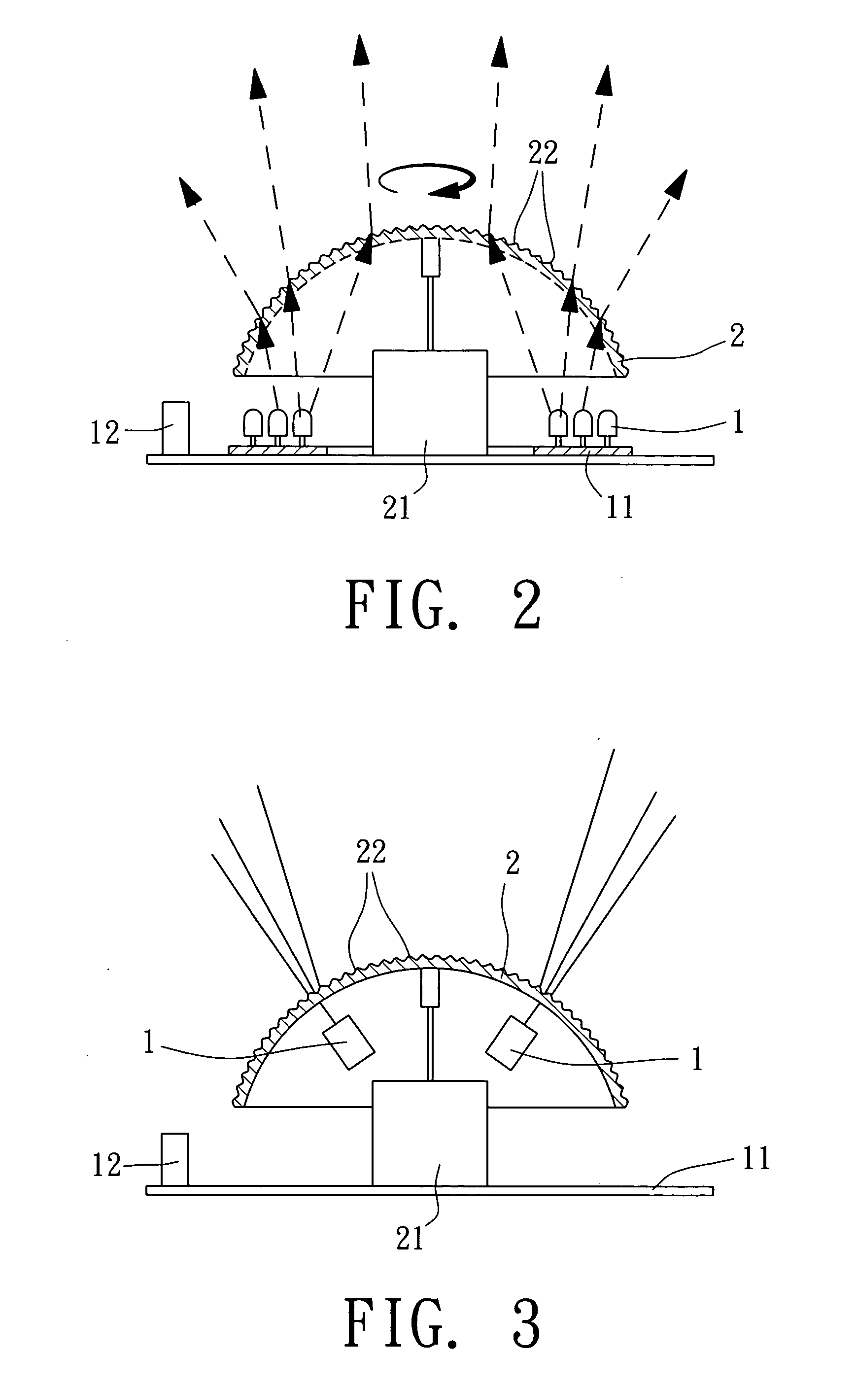
[0018] Referring to FIGS. 1 and 2, a lighting device in accordance with the present invention is shown comprised of a light source and a lens 2.

[0019] The light source comprises a circuit board 11, a plurality of light emitting devices 1 installed in the circuit board 11, and a programmable controller 12 adapted to control the operation (on / off and / or flashing) of the light emitting devices 11 subject to a predetermined program. The light emitting devices 1 can be regular LEDs (light emitting diodes), laser diodes (see FIG. 3), or a combination of LEDs and laser diodes (see FIG. 4). The light emitting devices 1 can be of the same color (see FIGS. 1 and 2). Alternatively, if the light emitting devices 1 are light emitting diodes, they can be made with different colors (see FIGS. 4 and 5). The color combination may include red, green and blue colors. Other color combinations (such as the combination of yellow, white and purple colors) are also possible.

[0020] The lens 2 is set in th...


PUM


Abstract

A lighting device is disclosed to include a light source formed of light emitting diodes and / or laser diodes and controlled to emit light and / or to flash by a programmable controller, a lens, which has raised portions for refracting the light of the light emitting diodes and / or laser diodes to produce a lighting effect, and a driving mechanism for rotating the lens relative to the light source.

Description

BACKGROUND OF THE INVENTION [0001] 1. Field of the Invention [0002] The present invention relates to lamps and more particularly, to a lighting device that uses a lens with raised portions to refract the light of LEDs and / or laser diodes and a driving mechanism to rotate the lens relative to the LEDs and / or laser diodes, thereby producing a lighting effect. [0003] 2. Description of the Related Art [0004] Following fast development of high technology, semiconductor light emitting devices, for example, LEDs (light emitting diodes) have been intensively used in signal lights, neon lights, light boxes, vehicle lamps, hand lamps, etc. to substitute for conventional incandescent and / or fluorescent bulbs for the advantages of low power consumption and low heat. Further, laser diodes are also intensively used in pointers, examination instruments, advertising apparatus. Further, when a laser light source is used to produce images of laser light, expensive peripheral apparatus (such as steppe...

Claims


Application Information

Patent Timeline
Patent Type & Authority Applications(United States)
IPC IPC(8): B60Q1/26
CPCF21S10/00F21S10/06F21V5/02F21V14/02F21V14/06F21W2121/00F21W2131/406F21Y2101/02F21Y2101/025F21Y2113/005F21V3/02F21Y2103/33F21Y2113/13F21Y2115/10F21Y2115/30
Inventor CHICH, ROBERT H.CHEN, CHUN-MING
Owner CHICH ROBERT H
Learn More