
Emergency lighting

a technology for emergency lighting and lighting, applied in the direction of discharge tube screens, fixed installations, electric batteries, etc., can solve the problems of system inoperable, power source and/or wiring damage of electrically powered lighting systems, etc., and achieve the effect of reducing the luminance level and reducing the tim

Active Publication Date: 2007-05-03
SAF T GLO
View PDF6 Cites 17 Cited by
  • Summary
  • Abstract
  • Description
  • Claims
  • Application Information

AI Technical Summary

Benefits of technology

[0009] In this way, the first material provides a high intensity (bright) light output for the initial operation of the emergency lighting and, as the intensity of the light output decays with time, the intensity of the light output from the second material decays more slowly for continued operation of the emergency lighting over an extended period of time.
[0017] The housing may include an internal partition wall extending between the upper and lower walls that divides the housing into two compartments—one for each strip of photoluminescent material—and supports the upper wall. In this way, the partition wall strengthens the housing and improves the load-bearing capability of the housing. As a result, the thickness of the upper wall can be reduced so that light transmission is improved without compromising the service life of the housing.
[0019] In a preferred arrangement, the photoluminescent material and sheet member are located in separate slots within the housing such that the sheet member can be fitted and removed independently of the photoluminescent material and vice versa. In this way, the housing can be assembled with or without the sheet member and the sheet member can be replaced when it is desired to change the appearance and / or function of the housing.
[0024] The partition wall supports the upper wall and improves the load bearing capability of the housing. The light emitting material may be the same on both sides of the partition wall or different. For example, the materials may have the same or different light emitting characteristics. The upper wall and lower wall of the housing may be a single component or separate components releasably secured together. Where the upper wall and lower wall are separate components, the partition wall may be provided as part of one component. Alternatively, each component may provide a part of the partition wall. Alternatively, the partition wall may be provided by a separate component for assembly with the components of the upper and lower wall.
[0030] According to a fifth aspect of the present invention, we provide a luminous substrate that emits light on being excited by exposure to light, the substrate having portions with different light emitting characteristics such that, in the absence of light to excite the substrate, the level of luminance provided by a first portion of the substrate reduces more quickly than the level of luminance provided by a second portion of the substrate.

Problems solved by technology

For example, in an emergency, the power source and / or wiring of an electrically powered lighting system may be damaged rendering the system inoperable at the very moment it is required.

Method used


Image

  • Emergency lighting
  • Emergency lighting
  • Emergency lighting

Examples


Embodiment Construction

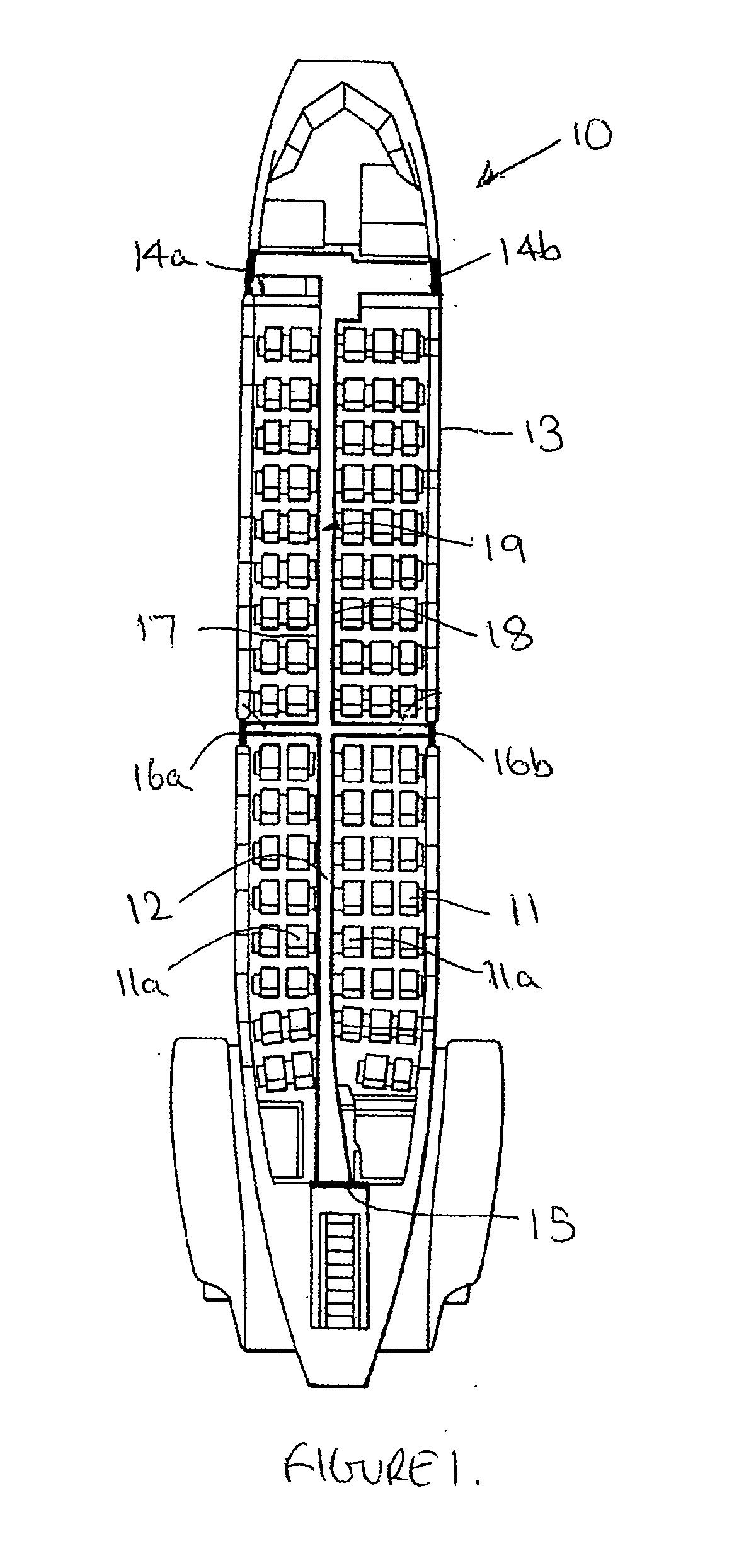
[0041] Referring first to FIG. 1 of the accompanying drawings, there is shown the general layout of a dual track floor proximity emergency lighting system in an aircraft 10. The aircraft 10 has a plurality of rows of seats 11 disposed on either side of a centre aisle 12 extending the length of the passenger compartment or cabin 13.

[0042] The cabin 13 is provided with a pair of exits 14a, 14b at the front end and an exit 15 at the rear end for passengers to get on and off the aircraft both in normal use and in an emergency. A further pair of exits 16a, 16b are provided on either side of the cabin 13 approximately mid-way between the ends of the cabin 13, usually opening over the wings (not shown) of the aircraft 10 and which are only used in an emergency.

[0043] The emergency lighting has a pair of tracks 17, 18 positioned on the floor along each side of the aisle 12 adjacent to the aisle seats 11a to define an aisle path 19 extending the length of the cabin 13 between the aisle sea...


PUM


Abstract

Emergency lighting for an aircraft employs a photoluminescent substrate that is activated by exposure to light wherein the substrate has portions with different light emitting characteristics whereby, in the absence of activating light, a first substrate portion provides a higher light output than a second substrate portion for an initial period after which the second substrate portion provides a higher light output than the first substrate portion.

Description

FIELD OF THE INVENTION [0001] This invention concerns improvements in or relating to emergency lighting and in particular, but not exclusively, to emergency lighting used to indicate an escape path leading to an exit for evacuation of a passenger vehicle in an emergency, for example following an accident or outbreak of a fire. [0002] The invention has particular application to passenger vehicles of the type in which rows of seats are provided on either side of an aisle with an exit at one or both ends of the aisle and / or on one or both sides of the aisle between the ends. Examples of this type of passenger vehicle include aircraft, trains and coaches. BACKGROUND OF THE INVENTION [0003] In our UK Patent No. GB 2314536-B we describe an emergency lighting system in which the path to the exit(s) is illuminated by photoluminescent material incorporated into a track extending along the aisle for passengers to follow to the exit(s). This system does not require connection to a power source...

Claims


Application Information

Patent Timeline
Patent Type & Authority Applications(United States)
IPC IPC(8): F21V9/16B60Q3/02G09F13/22
CPCB60Q3/0256B64D2011/0038G09F13/22B60Q3/46Y10S362/812
Inventor STOKES, PETER DAVIDO'KELL, SEAN PATRICK
Owner SAF T GLO
Learn More