[0019] The present inventors have recognized that forming the wound wire inductor 15 from wire, rather than
machining or
stamping the inductor has several advantages. A higher level of
inductance can be achieved, relative to a stamped or machined inductor of the same size, because a minimum spacing required for
stamping or
cutting tools is eliminated when an insulating
coating is applied to the wire before winding the inductor with the adjacent coils in contact with each other. Thereby, the overall size requirements of the inductor for a given
inductance is reduced. Also, wire winding equipment is relatively simple to configure for a desired inductor coil
diameter and length, allowing cost effective production of a wide range of different inductors with inductances selected in combination with any straight portion(s) of the wire wound inductor coil 15 for specific frequency bands.
[0020] Further, as the width between the
inductor windings is minimized, a
parasitic capacitance of the inductor is increased. While an ideal inductor has an increasing impedance with respect to increasing frequency, the presence of
parasitic capacitance has the inverse effect. Thereby, the interaction of both the inductive and capacitive effects creates a
self resonance frequency where the impedance of the inductor is maximized. By tuning the length of any linear portion(s), the number of turns,
diameter and coil to coil spacing of the wire wound inductor 15, the
inductance and
parasitic capacitance characteristics of the wire wound inductor may be adapted so that the
self resonance frequency is positioned at the center of the desired
frequency band. Thereby, the
insertion loss represented by the presence of the surge suppressor along the
coaxial cable may be minimized within the desired
frequency band. The
self resonance frequency characteristic of the wire wound inductor reduces the extent of a linear portion needed to avail the surge suppressor insert of
broadband characteristics, for example as disclosed in Aleksa et al., allowing a significant reduction in the overall size requirements for a surge suppressor according to the invention. Where desired, the linear portion(s) may be accommodated by extending the height of the hollow cap 19.
[0021] Additional tuning of the wire wound inductor 15 impedance characteristics may be applied by adjusting the
dielectric value of the material around which the inductor is wound and or that may be inserted between the adjacent individual coils. For example, a core material with a specific
dielectric value may be applied and or the wire wound inductor may be fully encapsulated in a
dielectric, for example as shown in FIG. 3. As shown for example in FIG. 4, an encapsulated wire wound inductor 15, hollow cap 19 and threaded contact 27, may be pre-assembled, to form an integral surge suppression insert 31. The surge suppressor insert 31 provides a ready to install
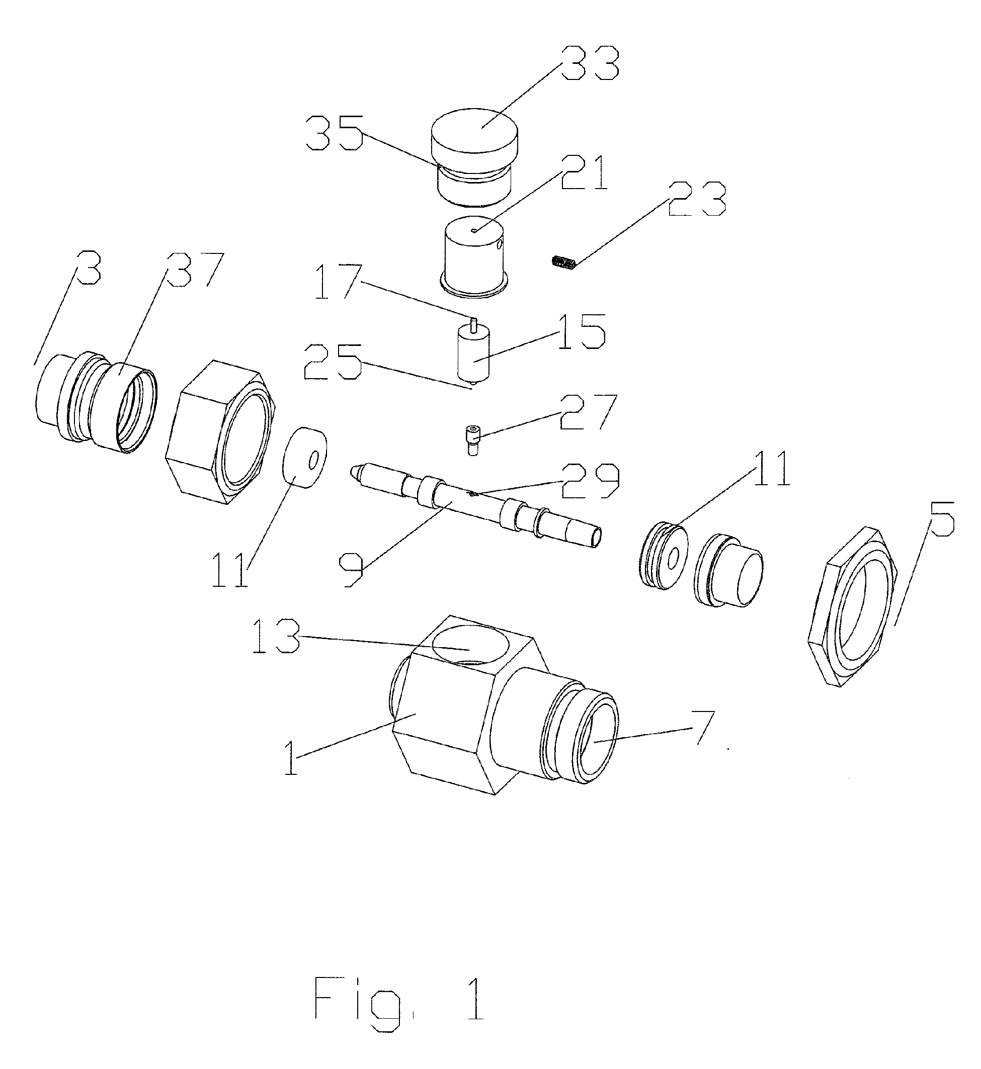
assembly that minimizes the chance for damage or loss of loose components prior to installation. One skilled in the art will appreciate that encapsulation of the wire wound inductor 15 and the hollow cap 19 of the surge suppression insert 31 both help to contain damage to the body 1 if the wire wound inductor 15 is subjected to an out of range and or repeated surge(s).
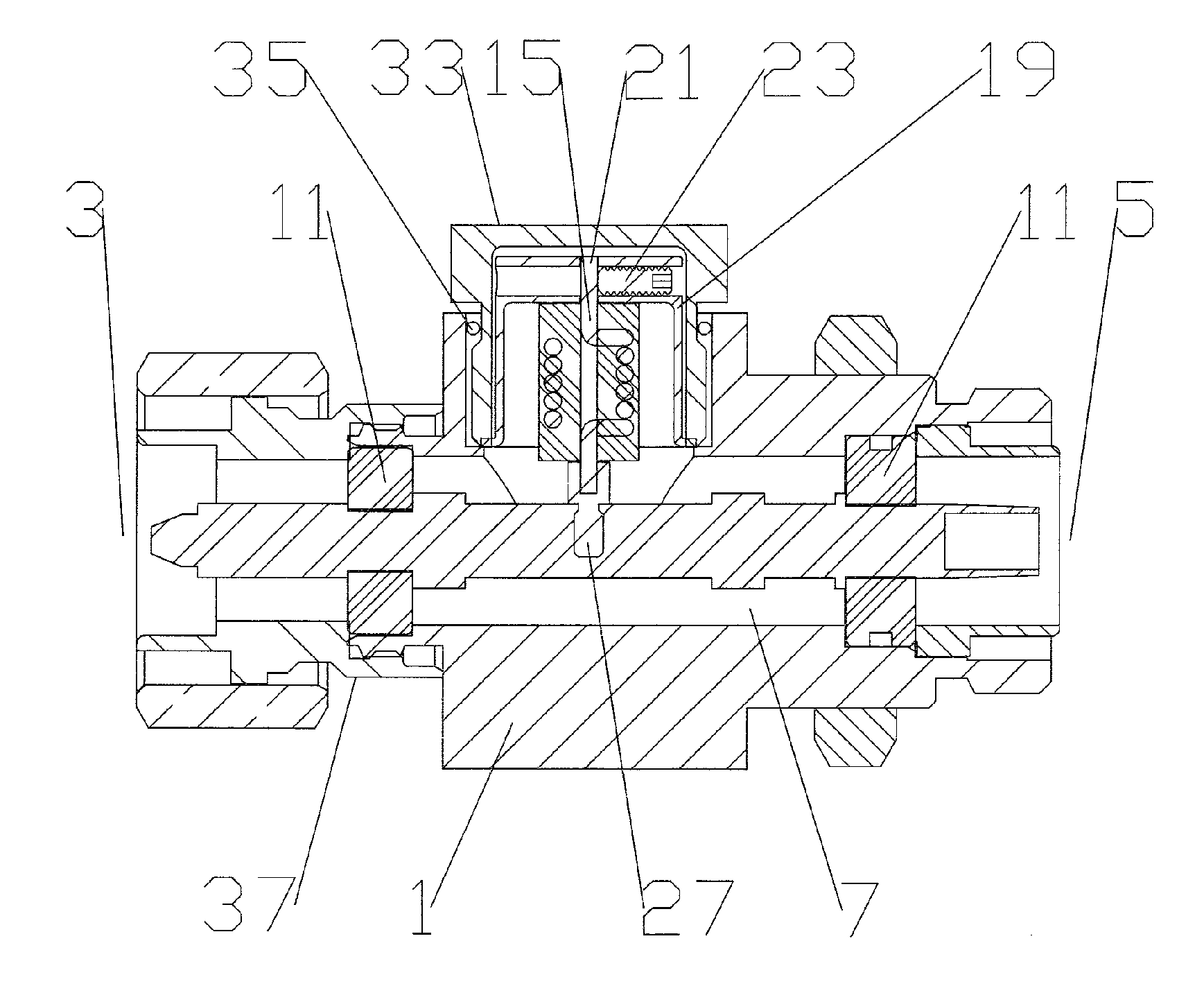
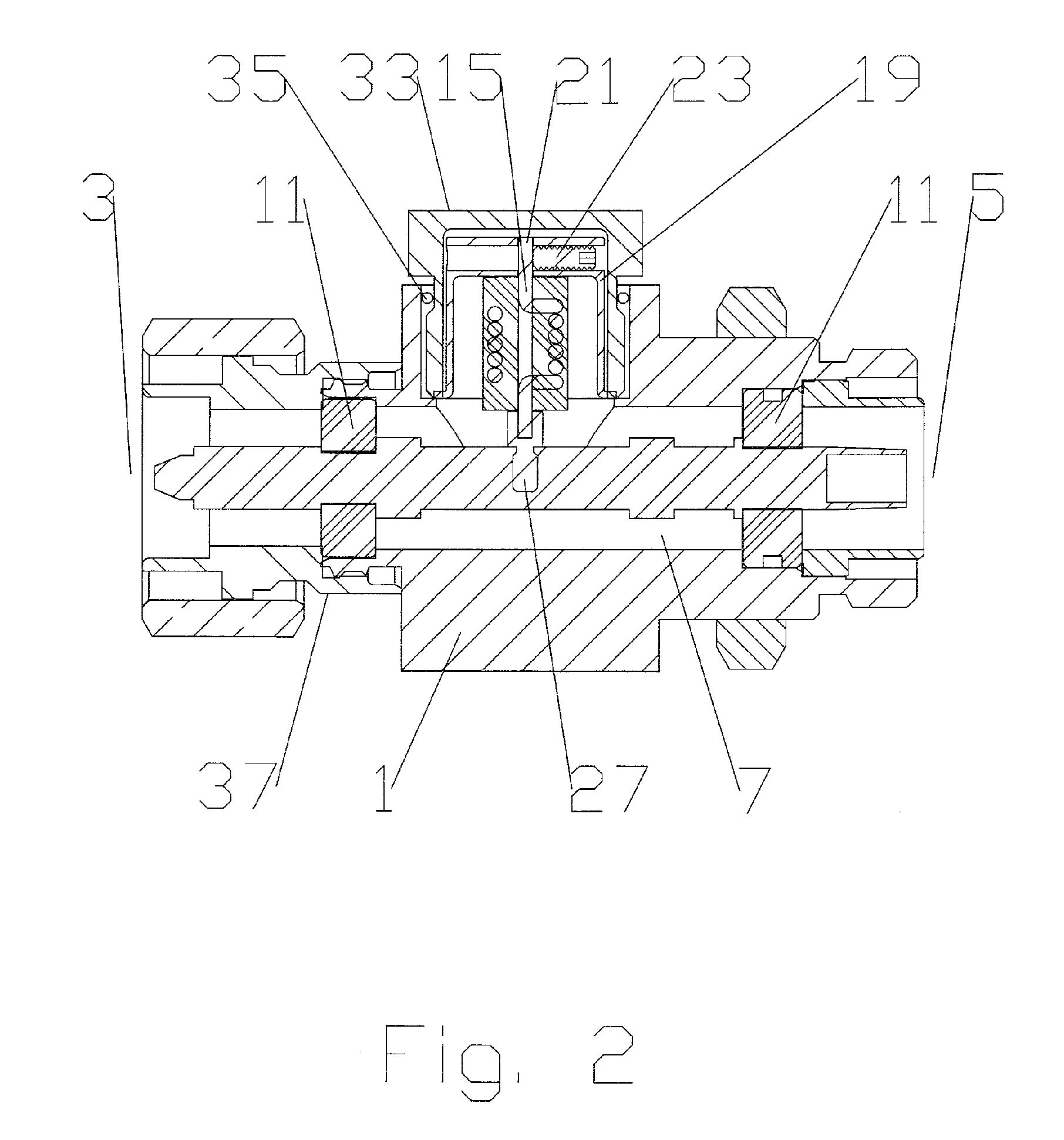
[0022] The hollow cap 19 may be held in place by a retaining cover 33 which threads into the body 1, biasing the hollow cap 19 into secure contact with the body 1. The retaining cap 19 may also include an environmental seal 35, such as an o-ring, to prevent
moisture migration into the body 1 and thereby into the connected coaxial cables and or equipment. A mounting point, such as a threaded hole, useful for mounting the surge suppressor to a desired location and or attaching a ground lead may also be formed in the body 1. While the surge suppressor insert 31 has been demonstrated for use with a dedicated body 1, it should also be appreciated that the surge suppressor insert 31 may be easily adapted for use with existing surge suppressor bodies originally supplied with other forms of surge suppression elements, such as quarter wave stubs and or helically machined inductor / stub combinations.
[0023] To simplify
assembly of the surge suppressor and or allow repair of a surge damaged surge suppressor, the body 1 may be formed to receive a
retainer element 37 that includes the first connection end 3. The
retainer element 37 allows the inner conductor 9 and associated insulator(s) 11 to be initially assembled and or exchanged and then securely retains the components in place. The
retainer element 37 may be coupled to the body, for example, via
mating threads and or an
interference fit. Alternatively, the retainer element 37 may be omitted and the inner conductor 9 mounted within the body by press fitting or injection molding the insulator(s) 11, about the pre-positioned inner conductor 9, within the bore 7.
[0024] One skilled in the art will appreciate that the present invention represents a significant improvement in size requirements, ease of use, manufacturing and
cost efficiency. The overall materials requirements,
machining operations and total number of discrete components are reduced. The readily exchangeable surge suppression insert(s) 31 according to the invention may be cost effectively manufactured for a wide range of different frequency bands. Also, surge suppressors according to the invention for specific frequency bands may be quickly assembled for on-demand delivery with minimal
lead time, eliminating the need for large stocks of pre-assembled frequency band specific surge suppressor inventory. Further, should a surge suppressor be damaged, or the desired frequency band of operation change, the surge suppression insert 31 may be easily exchanged by the user without disturbing connections to surrounding equipment. Table of Parts1body3first connection end5second connection end7bore9inner conductor11insulator13surge suppression insert mount15wire wound inductor17first end19hollow cap21hole23screw25second end27threaded contact29threaded hole31surge suppression insert33retaining cover35environmental seal37retainer element
