
IFOG modulation technique for real-time calibration of wavelength reference under harsh environment

a wavelength reference and modulation technology, applied in the field of interferometric fiber optic gyroscopes, can solve the problems of reducing the contrast of sensing interferometers, reducing the contrast of interferometers, and achieving zero light intensity at the photo detector level

Inactive Publication Date: 2007-05-03
HONEYWELL INT INC
View PDF6 Cites 29 Cited by
  • Summary
  • Abstract
  • Description
  • Claims
  • Application Information

AI Technical Summary

Benefits of technology

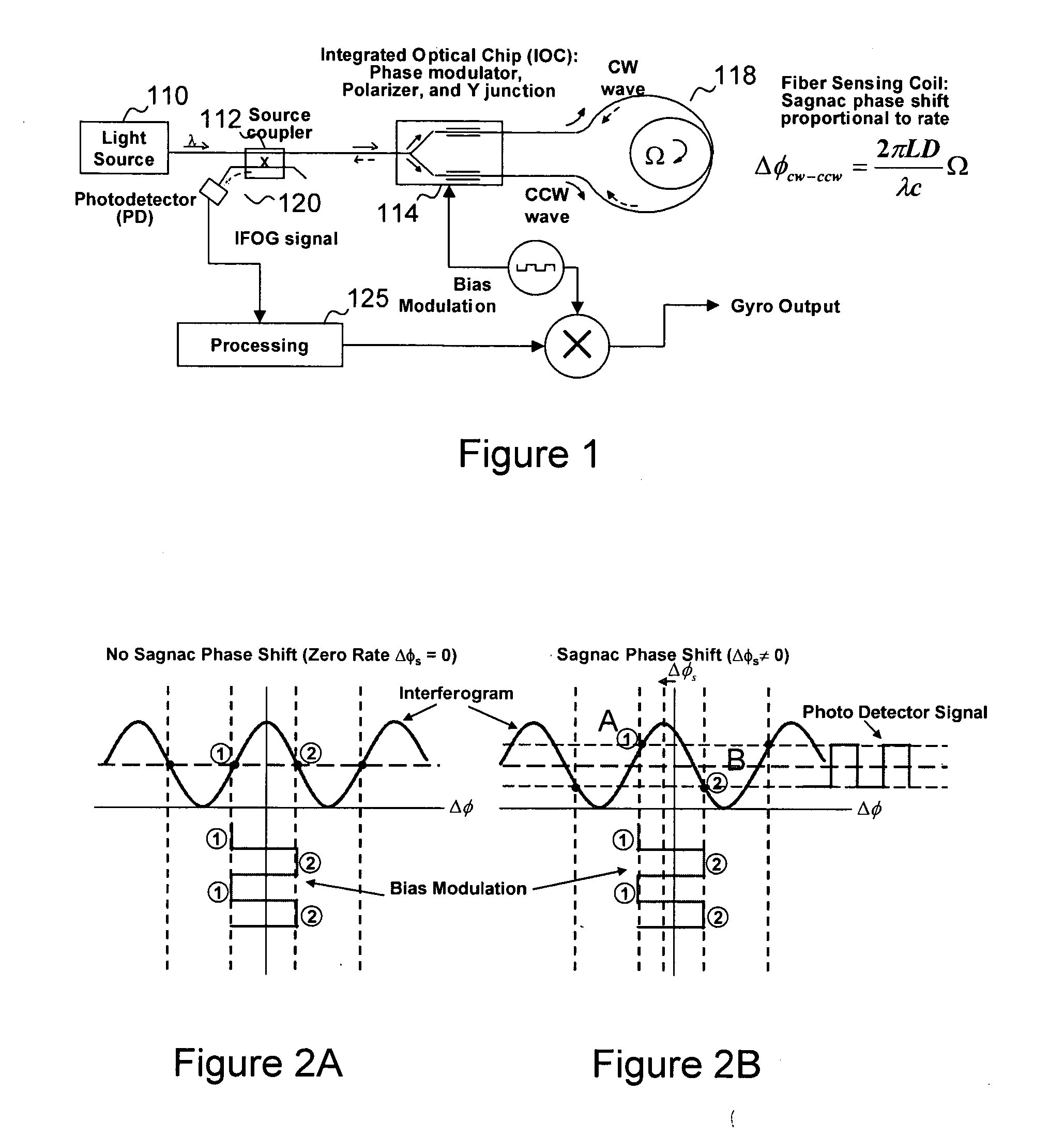
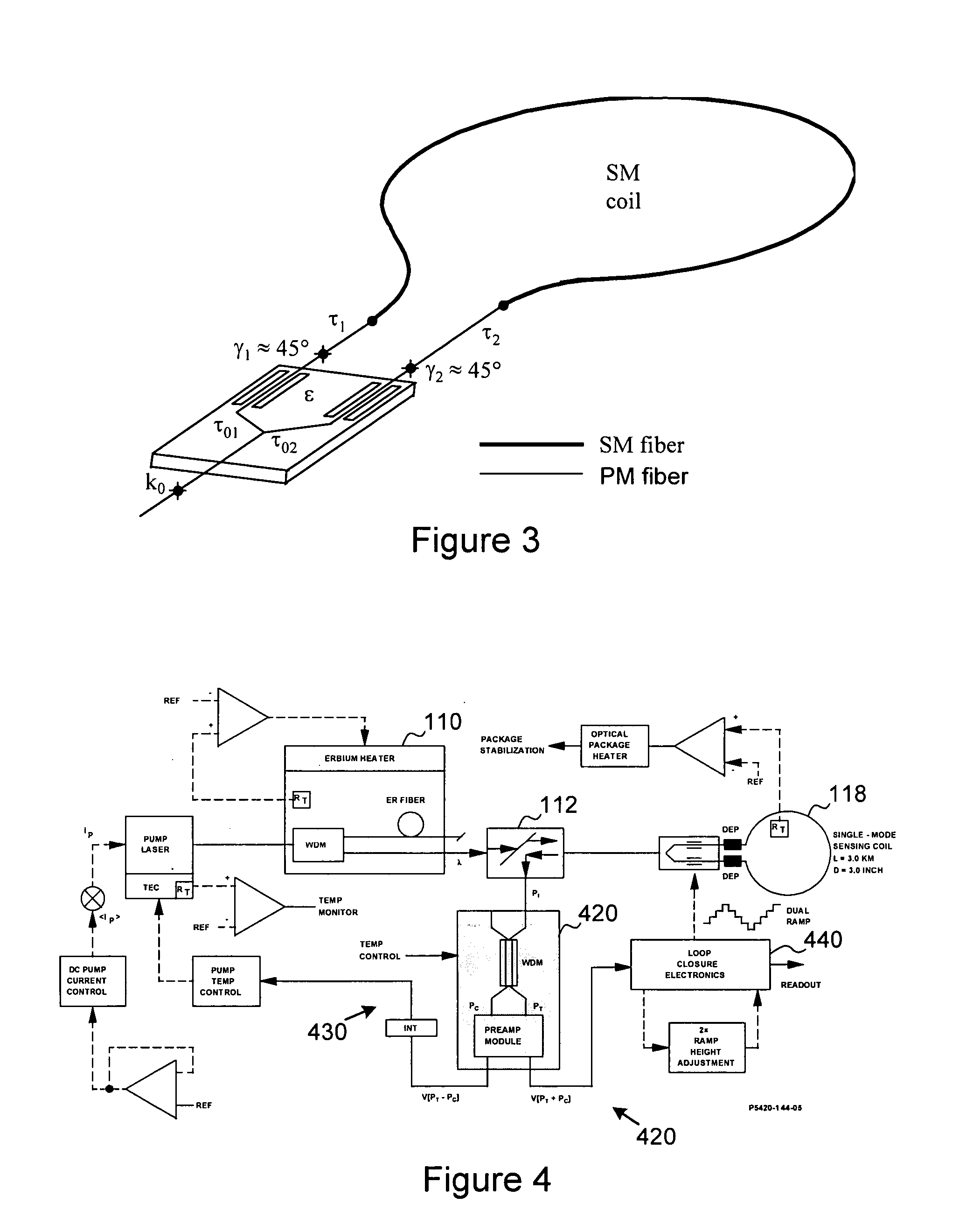
[0012] For an IFOG integrated with (i) a WDM-based wavelength control servo and (ii) an absolute wavelength reference for high accuracy scale factor performance under harsh environments, there is a need to independently modulate the gyro returned signal along with the wavelength reference / servo signals to separate these two signals for further processing and calibration. In accordance with embodiments of the present invention, only the gyro rate-induced signal is modulated, but not the wavelength reference signal. This approach allows for the continued use of known multi-function IOCs in the sensing loop to temporarily shut off the gyro signal. More specifically, during normal IFOG operation, the gyro is biased at a point other than π for integrated-rate signal retrieval. Periodically, at a preset interval, the gyro return signal is shut off by biasing the gyro at π or multiples of π. During this short shut off period, there is no gyro return signal. Consequently, the WDM error plus the mismatch between the two photodetectors can be calibrated with the external absolute wavelength reference. The wavelength calibration can be open-loop through measuring the power difference of the two photodetectors pigtailed to the WDM output leads.

Problems solved by technology

Without the polarizer the un-modulated light forms additional interference which reduces the contrast of the sensing interferometer.
At π (180°) phase difference, the interferogram shows destructive interference resulting in zero light intensity at the photo detector level.
While WDM-based wavelength control has significantly improved the IFOG's scale factor, some issues remain.

Method used


Image

  • IFOG modulation technique for real-time calibration of wavelength reference under harsh environment
  • IFOG modulation technique for real-time calibration of wavelength reference under harsh environment
  • IFOG modulation technique for real-time calibration of wavelength reference under harsh environment

Examples


Embodiment Construction

[0022] The very first fiber optic gyroscopes were constructed using single mode (SM) fiber. At that time, it became obvious that uncontrollable and environmentally dependent polarization evolution occurring in the SM fiber is manifested as bias drift and signal fading. The bias drift results from polarization errors while signal fading is a consequence of polarization wander. Polarization maintaining (PM) fiber, which appeared on the market in the early 1980s, offered properties which preserved the simplicity of the gyroscope architecture and at the same time offered a simple solution to the problems of signal fading and polarization errors. Therefore, the most prevalent design thus far has used PM fiber to meet the stringent performance requirements of navigation gyroscopes.

[0023] An effort to make FOG technology affordable triggered investigation in depolarized gyroscopes which use inexpensive SM fiber in the sensing loop. In recent years, a series of breakthroughs have advanced ...


PUM


Abstract

An interferometric fiber optic gyroscope (IFOG) includes a fiber light source, a multi-function integrated optic chip (IOC) and corresponding fiber sensing coil, and a wavelength division multiplexor connected to each other via a coupler, along with servo loop closure processing electronics. In addition, an absolute wavelength reference, such as an atomic reference, that is not susceptible to drift or effects of radiation, is connected to the wavelength division multiplexor. Periodically and momentarily, and for purposes of calibrating the wavelength division multiplexor, gyro return light from the IOC, which is normally passed to the wavelength division multiplexor, is suppressed in favor of a signal supplied by the absolute wavelength reference.

Description

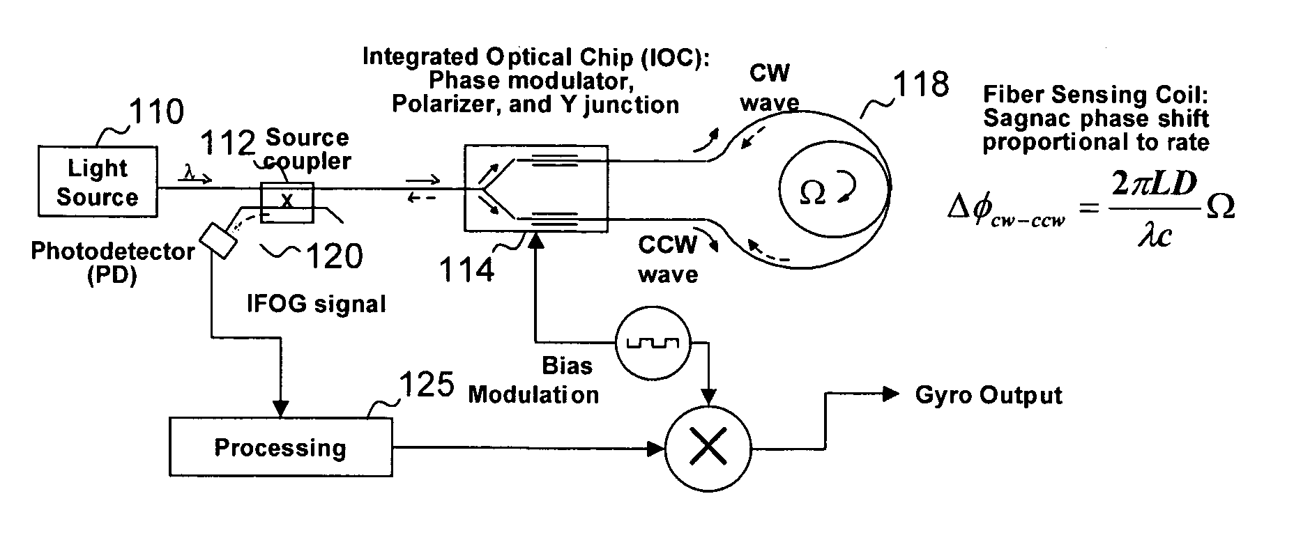
[0001] This invention was made with Government support under contract no. DL-H531279. The Government has certain rights in the invention.BACKGROUND [0002] 1. Field of the Invention [0003] The present invention relates generally to interferometric fiber optic gyroscopes (IFOGs) and improvements thereto. [0004] 2. Background of the Invention [0005]FIG. 1 illustrates the basic operation and fundamental components of an IFOG. The IFOG design comprises six major components: fiber light source 110, coupler 112, multi-function integrated optic chip (IOC) 114 containing Y-junction and phase modulators, fiber sensing coil 118, photo detectors 120 and processing electronics 125. Fiber light source 110 generates light, and sends the light to the fiber sensing loop 118 through source coupler 112 and IOC 114. The source coupler 112 takes the input light and splits it in half to send it through both output legs. One output leg takes the source light further to IOC 114. The other output leg can be...

Claims


Application Information

Patent Timeline
IPC IPC(8): G01C19/72
CPCG01C19/726
Inventor REN-YOUNG, LIU
Owner HONEYWELL INT INC
Learn More