
Phase switch and a standing wave linear accelerator with the phase switch

a technology of phase switch and standing wave electron linear accelerator, which is applied in the direction of accelerators, electric discharge tubes, electrical apparatus, etc., can solve the problems of accelerator not being able to function normally, the performance of electron beam output is seriously deteriorated, and the energy of such radiation beams is much higher than that required by medical imaging, etc., to achieve accurate positioning of the adjustment mechanism, simple energy switching, and stable operation

Active Publication Date: 2007-05-03
GUANGZHOU REPAIR MEDICAL TECH CO LTD
View PDF8 Cites 3 Cited by
  • Summary
  • Abstract
  • Description
  • Claims
  • Application Information

AI Technical Summary

Benefits of technology

[0017] To solve the above problems, this invention provides a phase switch capable of simple energy switching and stably operating in π / 2 mode without the problem of accurate positioning of the adjustment mechanism, and a standing wave electron linear accelerator for medical use that is formed by using the phase switch.
[0020] By using the phase switch and the electron linear accelerator according to this invention, the problems existed in the prior art such as low structure performance and operation stability, fire-striking, low coupling efficiency, low flexibility, and the requirement of accurate positioning reset can be overcome.

Problems solved by technology

However, the energy of such radiation beams are much higher than that required by medical imaging.
When the power is decreased to a certain value, the relationship of field intensity and phase velocity in the beam focus segment goes far away from the design value, the performance of electron beam output is seriously deteriorated and trapping is greatly reduced so that the accelerator cannot function normally.
However, under this status, the field intensity in the coupling cavity is very high, and any moving components would cause high-frequency fire striking.
During phase inversion, it is difficult to adjust field intensity separately.
However, all the technologies above improve the performance of the low-energy electron beam outputted by the accelerator by changing coupling coefficients to increase the field intensity of the beam focus segment, while do not incorporate phase inversion.
However, according to the recitations in the description of this patent application, the frequency of the cylindrical coupling cavity would change when the polarization plane rotates so that the performance of the structure and the stability of operation are affected.
Besides, since the device operates under a high order mode TE111, it may be easily affected by other adjacent high order modes during operation.
Since there's still field intensity existed in the cylindrical coupling cavity, the device is not strictly operating in π / 2 mode and also has the problem of fire striking.
All these problems affect the operation stability of the device.
In addition, the adjusting in the adjustment mechanism is not convenient, and has a low flexibility.

Method used


Image

  • Phase switch and a standing wave linear accelerator with the phase switch
  • Phase switch and a standing wave linear accelerator with the phase switch
  • Phase switch and a standing wave linear accelerator with the phase switch

Examples


first embodiment

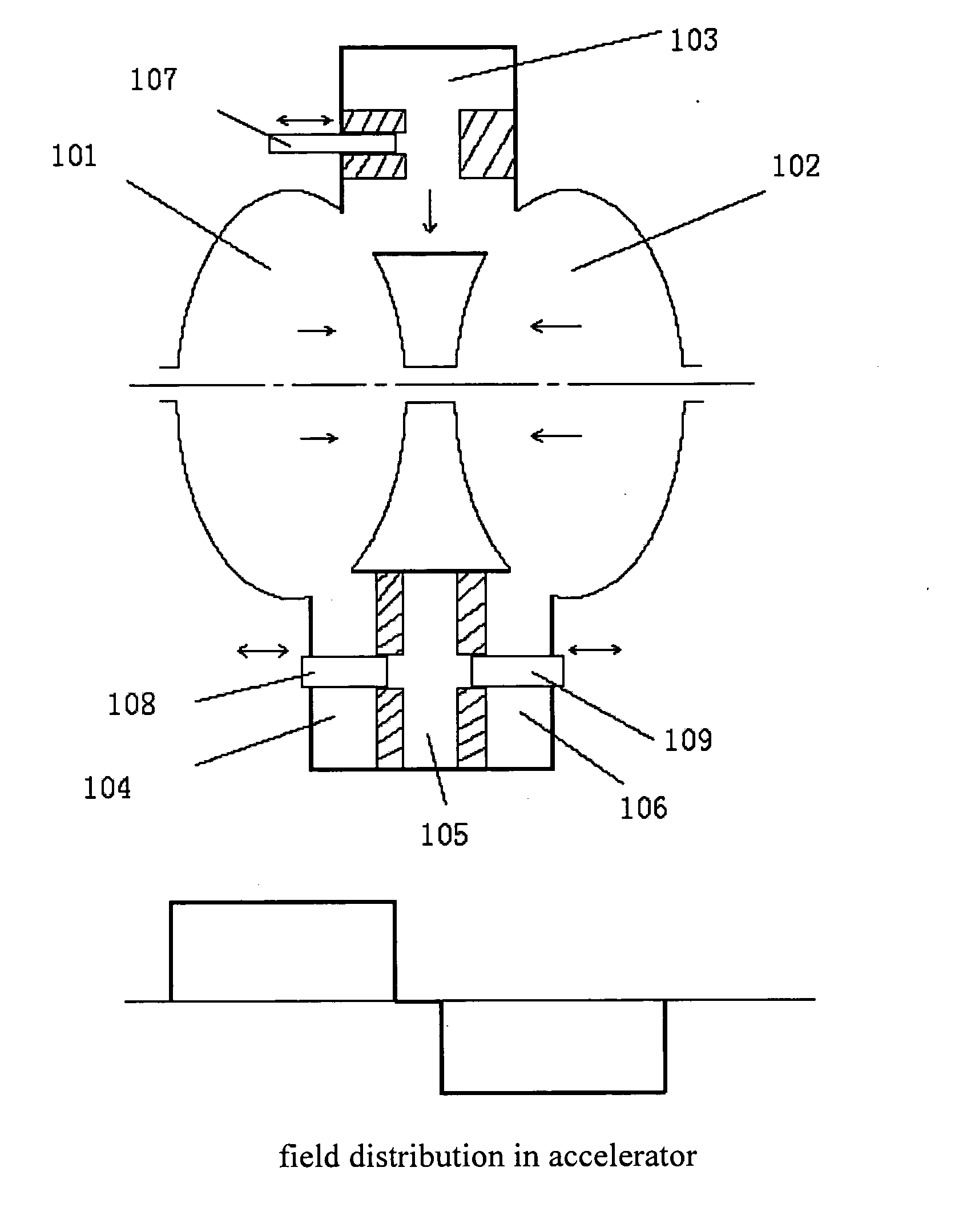
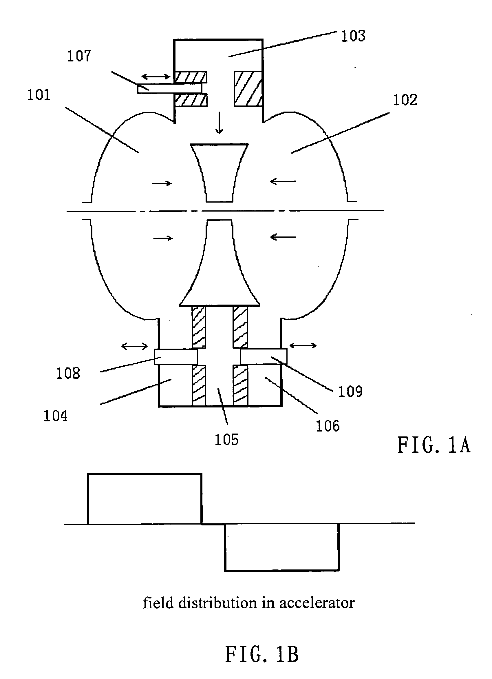
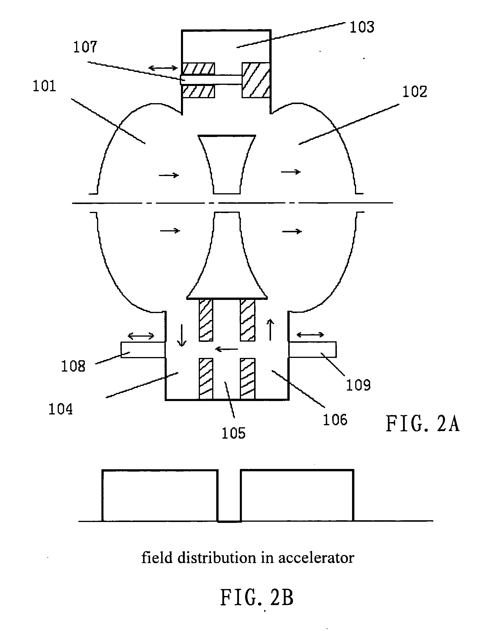
[0028]FIGS. 1A and 1B show a status of a phase switch according to this invention and its field distribution in its adjacent accelerating cavities, respectively, where the status is also referred to as a normal status “0”. The electrons meet an accelerating field after it reaches the accelerating cavity right after the phase switch. Numerals 101 and 102 in FIG. 1A refer to accelerating cavities, numeral 103 refers to a single coupling cavity in the phase switch, numerals 104 and 106 refer to end-coupled cavities, numeral 105 refers to side-passed accelerating cavities, numerals 107, 108, 109, and 116 are parts used in a deresonance cavity. Though only two adjacent accelerating cavities 101 and 102 are shown in FIG. 1A, the electron accelerator can include a plurality of (at least two) accelerating cavities having axes therein aligned that are arranged in parallel. The adjacent accelerating cavity 101 and 102 are connected via a coupling unit (i.e., the phase switch composed of a tri...

second embodiment

[0036]FIG. 3A shows another arrangement of a phase switch according to this invention. This arrangement is especially suitable for the accelerators in wave band x. Like parts in FIG. 3A are referenced by use of the same reference numerals as in FIG. 1A. Further, numeral 110 refers to a drift space, numeral 111 refers to a focus or deflection element. In general, the energy of electrons at the position of phase switch is already very high. A drift space 110 with a length of λ / 2 can be disposed. A focus or deflection element 111 can be disposed as desired in the drift space. This kind of arrangement can provide more vertical spaces for the phase switch. For the phase switch, the two arrangements have no difference. But for the operation of the accelerator, the functions of the two status of the phase switch would be exactly reversed. This kind of arrangement is especially suitable for the accelerators in wave band x. The length of the drift space can also be increased to λ, 3λ / 2. . .

[...

third embodiment

[0038]FIG. 4A shows a phase switch according to this invention. Assuming that k1 is the coupling coefficient of the accelerating cavity 101 and the end-coupled cavity 102 in the phase switch, k2 is the coupling coefficient of the end-coupled cavity 104 and side-passed accelerating cavity 105, k3 is the coupling coefficient of the side-passed accelerating cavity 105 and the end-coupled cavity 106, k4 is the coupling coefficient of the end-coupled cavity 106 and the accelerating cavity 102, k5 is the coupling coefficient of the accelerating cavity 101 and the single coupling cavity 103 in the phase switch, and k6 is the coupling coefficient of the single coupling cavity 103 and the accelerating cavity 102. When it is required to asymmetrically design the phase switch, for example, k4 is greater than k1, then the field intensity of the following accelerating segments are decreased when the phase is inversed. Referring back to the arrangements in FIGS. 1A and 2A. As mentioned before, wh...


PUM


Abstract

A phase switch (energy switch) comprising a three-cavity system (an end-coupled cavity+side-passed accelerate cavity+an end-coupled cavity) and a separate single couple cavity is disclosed. The phase shift between the adjacent accelerate cavities is π when the three-cavities system is disordered (state ‘0’); and a microwave pass through the three-cavities system to the adjacent accelerate cavities, the phase between the adjacent accelerate cavities is change to 2π (or 0) when the single couple cavity is disordered (state ‘1’). When the state 0changes to state 1, the field phase in the structure behind the system is changed to π, thereby to switch the phase. In the two states, the entire structure operates in π / 2 mode, that is very stable. That is very important for the medical accelerator. The detaining components have been moved outside the cavity when the single couple cavity or the three-cavity system is in the operate state, without warring about high frequency breakdown. By changing couple between the two end-coupled cavities in the three-cavity system and the adjacent accelerate cavities and between the cavities in the system, the relative field-strength in the acceleration section besides the switching is changed while the phase reverses. It can be used for 6 Mev accelerator middle-energy or high-energy accelerator.

Description

TECHNICAL FIELD [0001] The invention relates to a phase switch and a standing wave electron linear accelerator formed by using the phase switch, more specifically, to a phase switch stably operating in π / 2 mode and a standing wave electron linear accelerator for medical use that is formed by using the phase switch. BACKGROUND ART [0002] Standing wave electron linear accelerators are widely used in radiation treatment. It has been a research direction over the past thirty years to extend the operating energy range, that is, to increase the output dosage over middle-energy and high-energy accelerators and to implement multiple purposes on one machine. The “Image Guided Radiation Treatment” (IGRT) is primary research direction in recent years. The related patents are as below: [0003] 1. U.S. Pat. No. 4,286,192 A, Tanabe et al., Varian, August 1981; [0004] 2. U.S. Pat. No. 4,382,208 A, Meddaugh et al., Varian, May 1983; [0005] 3. U.S. Pat. No. 4,629,938 A, Whitham, Varian, December 1986...

Claims


Application Information

Patent Timeline
IPC IPC(8): H05H9/00H05H7/12H05H9/04
CPCH05H9/04
Inventor YAO, CHONGGUO
Owner GUANGZHOU REPAIR MEDICAL TECH CO LTD
Learn More