Vehicle drive unit

a technology of drive unit and vehicle, which is applied in the direction of electric propulsion mounting, braking system, tractors, etc., can solve the problems of deteriorating drive feeling and long time for the wheel to grip the road surface, and achieve the effect of easy gripping of the road surface, and easy enlargement of vehicle driving for

Inactive Publication Date: 2007-05-03
HITACHI LTD
View PDF13 Cites 12 Cited by
  • Summary
  • Abstract
  • Description
  • Claims
  • Application Information

AI Technical Summary

Benefits of technology

[0017] In accordance with the present invention, it is possible to enlarge the vehicle driving force by pulsating the torque applied to the wheel under the slip state. Further, there is obtained an effect that the enlargement of the vehicle driving force makes to accelerate the vehicle and thus, the wheel can easily grip the road surface. Further, it is possible to suppress a vibration and an undesired sound in the grip state or at a time of traveling at a high velocity.

Problems solved by technology

However, in the method of reducing the motor torque step by step until the wheel grips the road surface, while executing the slip judgment as in the drive method mentioned above, it takes a long time for the wheel to grip the road surface.
Accordingly, a drive feeling is deteriorated, and if the tire keeps slipping, snow and ice thaw to form a water screen.

Method used


Image

  • Vehicle drive unit
  • Vehicle drive unit
  • Vehicle drive unit

Examples


Embodiment Construction

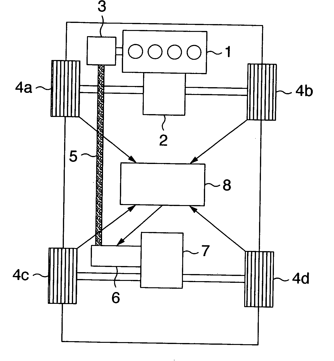
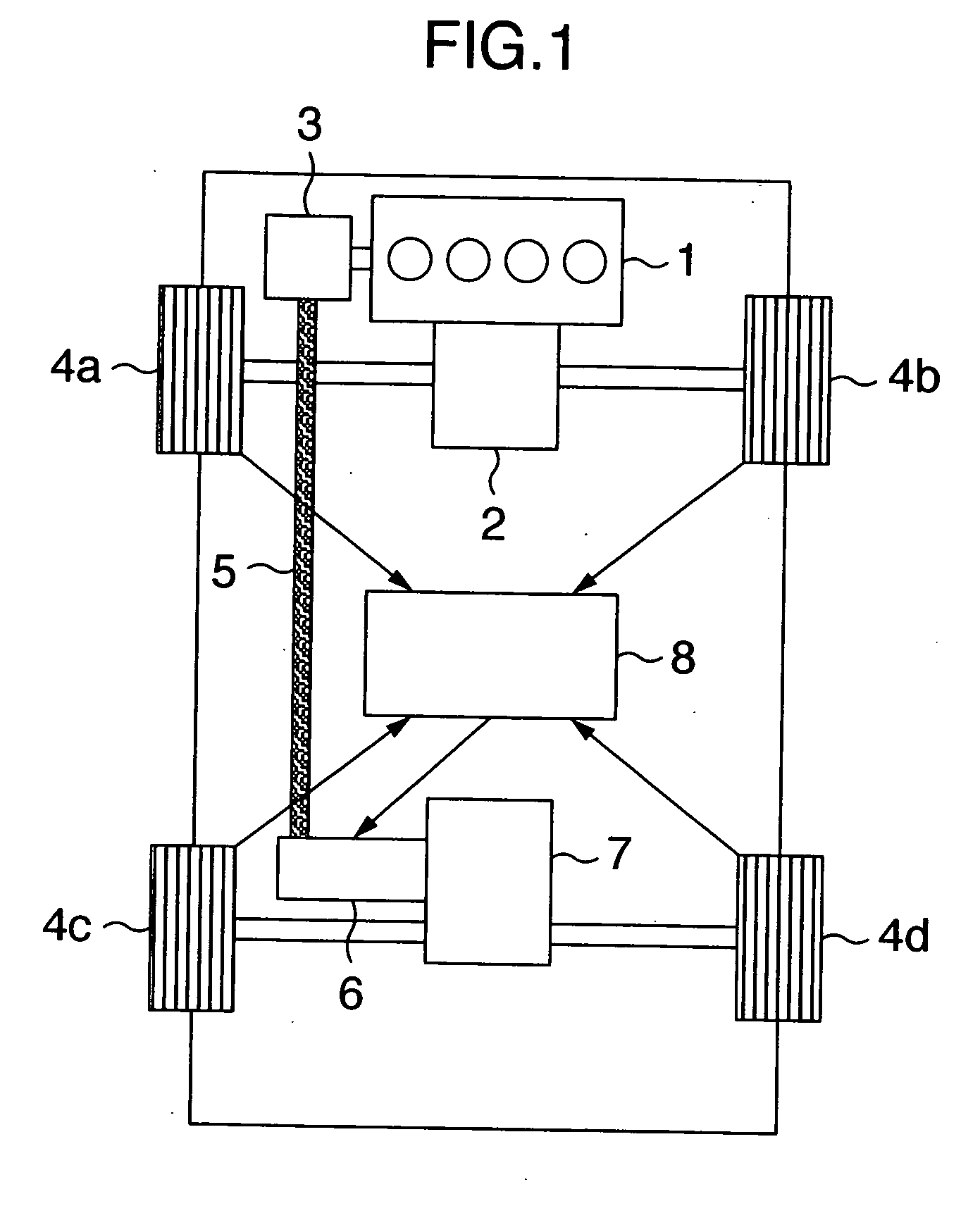
[0026] An example of a vehicle to which the present invention is applied is shown in FIG. 1. A description will be given below of the vehicle in FIG. 1. A power generated by an engine 1 is transmitted to a transmission 2 and a power generator 3. The power transmitted to the transmission 2 is divided into left and right so as to be transmitted to front wheels 4a and 4b. The power generator 3 executes a power generation by using the power transmitted from the engine 1, and supplies an electric power to a motor 6 via a power line 5. The motor 6 generates a power on the basis of the electric power supplied from the power generator 3. The power generated in the motor 6 is transmitted to a rear differential 7. The power transmitted to the rear differential 7 is divided into left and right so as to be transmitted to rear wheels 4c and 4d. A motor controller 8 controls the motor 6 on the basis of the method mentioned below in correspondence to velocitys of the wheels 4a, 4b, 4c and 4d.

[002...


PUM


Abstract

A vehicle drive unit, for quickly recovering a grip even if a wheel slips, in which in a slip state or at a time when the slip state is going to be generated, by pulsating a torque applied to the wheel, an angular velocity W of the wheel is changed so as to change the slip ratio S close to a slip ratio at which a friction coefficient becomes maximum, and thus, an average of a friction coefficient μ is enlarged and an average of a vehicle driving force F generated by a wheel is enlarged. Since the vehicle driving force is enlarged, the vehicle is accelerated and is easily gripped. Further, in a grip state or at a time of traveling at a high velocity, a vibration and an undesired sound are suppressed by doing away with the torque pulsation or making the fluctuation band of the torque pulsation small.

Description

FIELD OF THE INVENTION [0001] The present invention relates to a drive unit of a vehicle such as a motor vehicle or the like, and more particularly to a way for applying a power to a wheel and a structure for applying the power. DESCRIPTION OF THE RELATED ART [0002] As a drive system for securing a traveling performance at a time of traveling on a road surface having a small friction coefficient such as a snowy road and a frozen road surface, there is, for example, a method disclosed in JP-A-8-182118. In this method, it is judged whether or not the wheel slips while driving the wheel by a motor so as to travel. If the slip is judged to be generated, a process of reducing a torque command value to the motor a little is conducted. This process is repeated to continuously get down the torque command value to the motor until no slip is judged in the slip judgment. [0003] However, in the method of reducing the motor torque step by step until the wheel grips the road surface, while execut...

Claims


Application Information

Patent Timeline
Patent Type & Authority Applications(United States)
IPC IPC(8): B60L8/00B60L9/16
CPCB60K6/44B60K6/52B60K28/16B60T8/175B60W10/08B60W20/00Y02T10/623Y02T10/6265Y02T10/7258Y02T10/62Y02T10/7072Y02T10/72B60W20/15
Inventor IMURA, SHINYAKOWATARI, TAKEHIKOYAMAMOTO, TATSUYUKIITO, MASARU
Owner HITACHI LTD
Why Eureka
Try Eureka