Common-mode current cancellation with digital pulses for isolated applications

Active Publication Date: 2007-04-26
NATIONAL INSTRUMENTS
View PDF11 Cites 12 Cited by
  • Summary
  • Abstract
  • Description
  • Claims
  • Application Information

AI Technical Summary

Benefits of technology

[0008] In one embodiment, the first subsystem may include a pulse generation unit and compensation circuitry. The pulse generation unit may provide a first pulse and a second pulse to the compensation circuitry. The compensation circuitry may generate a cancellation signal based on the first and second pulses. Furthermore, the compensation circuitry may provide the cancellation signal to a ground plane of the isolated subsystem to reduce the common-mode current received at the isolation subsystem.

Problems solved by technology

A typical problem with systems implementing isolation applications is the common-mode current that flows from the non-isolated primary to the isolated secondary through the parasitic capacitance inside the transformer.
The common-mode current may interfere with the signals in the I / O channel of the isolated subsystem and may potentially cause interference in a customer's circuit or system that is connected to the isolated subsystem.
However, the grounded shield usually increases the transformer size, cost, and complexity.
However, the potentiometer solution typically increases the parts count and cost of the system.

Method used


Image

  • Common-mode current cancellation with digital pulses for isolated applications
  • Common-mode current cancellation with digital pulses for isolated applications
  • Common-mode current cancellation with digital pulses for isolated applications

Examples


Embodiment Construction

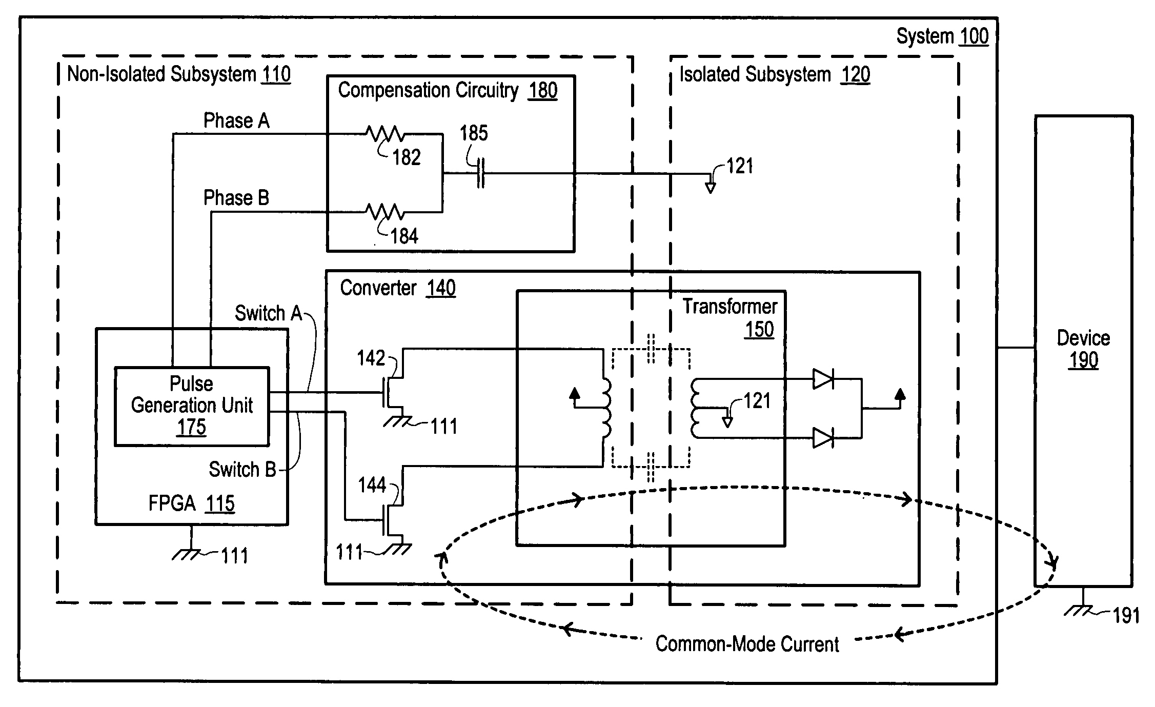
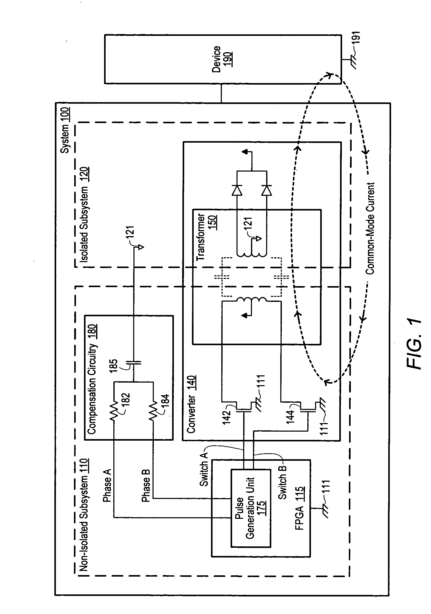
[0017]FIG. 1 is a diagram of one embodiment of a system 100 including a mechanism for reducing common-mode current in an isolated subsystem 120. As illustrated, the system 100 includes a non-isolated subsystem 110 and an isolated subsystem 120. During operation, a common-mode current may flow from non-isolated subsystem 110 to isolated subsystem 120. In one embodiment, circuitry within non-isolated subsystem 110 provides a first and a second pulse to a compensation circuit to generate a cancellation signal. The cancellation signal is injected into the isolated ground of the isolated subsystem 120 to reduce the common-mode current received at isolated subsystem 120.

[0018] System 100 may be a card or board plugged into one of the I / O slots of a computer system (see FIG. 5), or a card or board plugged into a chassis. System 100 may also be any of various types of computing or processing systems, including a personal computer system (PC), mainframe computer system, server system includ...


PUM


Abstract

A mechanism for reducing common-mode current in a system including a first subsystem and an isolated subsystem. The isolated subsystem may receive the common-mode current from the first subsystem via an isolation mechanism. The isolation mechanism (e.g., a transformer) may isolate the isolated subsystem from the first subsystem by blocking DC signals. The first subsystem may include a pulse generation unit and compensation circuitry. The pulse generation unit may provide a first pulse and a second pulse to the compensation circuitry. The phase and duty cycle of the pulses may be varied based on measured characteristics of the isolation mechanism. The compensation circuitry may generate a cancellation signal based on the first and second pulses. Furthermore, the compensation circuitry may provide the cancellation signal to a ground plane of the isolated subsystem to reduce the common-mode current received at the isolation subsystem.

Description

BACKGROUND OF THE INVENTION [0001] 1. Field of the Invention [0002] This invention relates to noise cancellation techniques and, more particularly, to common-mode current cancellation techniques for isolated applications. [0003] 2. Description of the Related Art [0004] A push-pull DC-DC converter may be used to generate isolated power supplies in a system including a non-isolated subsystem and an isolated subsystem. The transformer of the DC-DC converter may provide the power necessary for operation of the circuitry in the isolation subsystem. In addition, the transformer may provide isolation between the non-isolated subsystem and the isolated subsystem by blocking DC signals. [0005] A typical problem with systems implementing isolation applications is the common-mode current that flows from the non-isolated primary to the isolated secondary through the parasitic capacitance inside the transformer. The common-mode current may interfere with the signals in the I / O channel of the iso...

Claims


Application Information

Patent Timeline
IPC IPC(8): H02M3/335
CPCH02M1/14H02M3/3372
Inventor JOHNSTON, LEE H.
Owner NATIONAL INSTRUMENTS
Why Eureka
Try Eureka