
Method for adaptive feed rate regulation on numerically controlled machine tools

a numerically controlled machine tool and feed rate regulation technology, applied in the direction of electric programme control, program control, instruments, etc., can solve the problems of large effort, large processing surface of workpieces, and increased power, and achieve the effect of simple and safe operation

Inactive Publication Date: 2007-04-19
DR JOHANNES HEIDENHAIN GMBH
View PDF5 Cites 11 Cited by
  • Summary
  • Abstract
  • Description
  • Claims
  • Application Information

AI Technical Summary

Benefits of technology

[0006] Example embodiments of the present invention provide a method for adaptive feed rate regulation for a numerically controlled machine tool, which makes possible using the feed rate regulation for each NC program in a simple and safe manner, e.g., without having to undertake adjustments in the NC program itself.
[0011] Consequently, since no programming effort is required for processing any desired NC program using an adaptive feed rate regulation, significant advantage may be obtained from such a method, without great effort. The operation time of a tool is able to be reduced, the wear of a tool is able to be monitored, and greater damage is able to be avoided in response to a tool fracture. Since all these benefits are possible without effort, the positive effect of an adaptive feed rate regulation becomes available substantially more simply, and with that, the corresponding method becomes applicable in a broader sense.

Problems solved by technology

Thus, the power is greater, the harder the processed workpiece, and the larger the processed surface of the workpiece.
Conventional adaptive feed rate regulations, however, are believed to have the disadvantage that, in order to use the adaptive feed rate regulation, certain commands have to be taken up into each NC program in order to control the feed rate regulation itself.
This means that each NC program, for which the adaptive feed rate regulation is to be used, has to be prepared for it with great effort.
For NC programs for processing only a small number of pieces, this is not worthwhile.

Method used


Image

  • Method for adaptive feed rate regulation on numerically controlled machine tools
  • Method for adaptive feed rate regulation on numerically controlled machine tools

Examples


Embodiment Construction

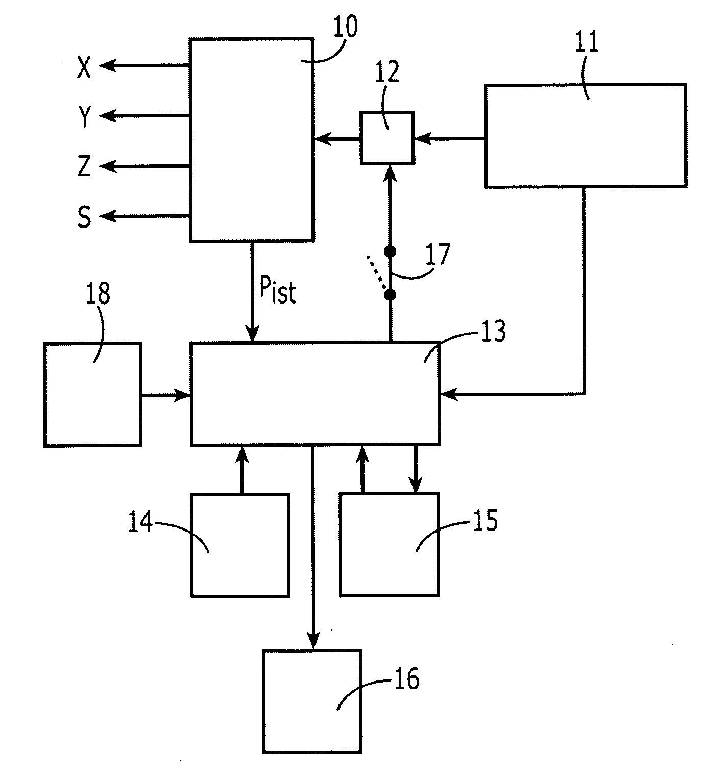
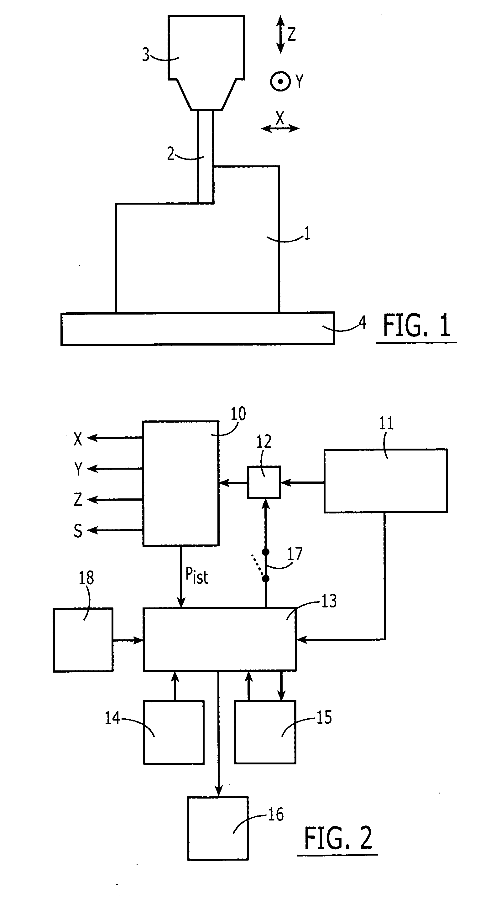
[0025]FIG. 1 schematically illustrates a section of a machine tool. A workpiece 1 is mounted on a table 4. As illustrated in FIG. 1, the workpiece 1 is being worked on by a tool 2 (e.g., a milling tool), which is fastened to a spindle 3, and is rotated, e.g., at great rotary speed by this spindle 3.

[0026] Tool 2 is movable with respect to workpiece 1 in three directions X, Y, Z. Other machine tools are able to permit further or different directions of motion between tool 2 and workpiece 1, for example, by additional swivel axes.

[0027] The input power of spindle 3 depends on at what feed and at how much contact area with workpiece 1 milling cutter 2 is being moved. Thus, the input power is relatively small if spindle 3 is already rotating at setpoint rotary speed, but milling tool 2 is not yet in contact with workpiece 1. The spindle power is very large if milling cutter 2 is being moved very rapidly and at large contact area through workpiece 1. The spindle then has to perform the...


PUM


Abstract

In a method for the adaptive feed rate regulation on a numerically controlled machine tool, which is used for the metal-removing processing of workpieces using a tool rotating on a spindle according to the specification of an NC program, the input power of the spindle is held as constant as possible by the influence of a tool feed rate established in the NC program for the motion between the tool and the workpiece. The method for the adaptive feed rate regulation is activated by a command of the NC program that initiates the processing of the workpiece, and is deactivated by a command of the NC program that terminates the processing of the workpiece.

Description

CROSS-REFERENCE TO RELATED APPLICATIONS [0001] The present application claims priority to Application No. 10 2005 041 175.4, filed in the Federal Republic of Germany on Aug. 31, 2005, which is expressly incorporated herein in its entirety by reference thereto. FIELD OF THE INVENTION [0002] The present invention relates to a method for the adaptive feed rate regulation on numerically controlled machine tools. Such methods may make possible an optimal utilization of the possibilities of a machine tool in interaction with numerical control. BACKGROUND INFORMATION [0003] A numerically controlled machine tool (CNC) executes an NC program in which various processing steps are specified one after another. For a milling machine, the relative motions between a workpiece and a tool are established and processed one after another. The milling cutter fastened to a rotating spindle removes material from the workpiece. In an NC program, besides the actual processing steps, tasks such as changing ...

Claims


Application Information

Patent Timeline
IPC IPC(8): G06F19/00
CPCG05B19/4163G05B2219/49065G05B2219/49078G05B2219/49092
Inventor FRAUNHOFER, HERMANN
Owner DR JOHANNES HEIDENHAIN GMBH
Learn More