
Predistorter for use in a wireless transmitter

a wireless transmitter and predistorter technology, applied in the direction of digital transmission, amplifier modification to reduce non-linear distortion, baseband system details, etc., can solve the problems of spectral broadening and in-band distortion, increase the cost, and affect the complexity of the overall predistorter implementation, so as to reduce the cost of wireless equipment

Inactive Publication Date: 2007-04-19
THOMSON LICENSING SA
View PDF4 Cites 31 Cited by
  • Summary
  • Abstract
  • Description
  • Claims
  • Application Information

AI Technical Summary

Benefits of technology

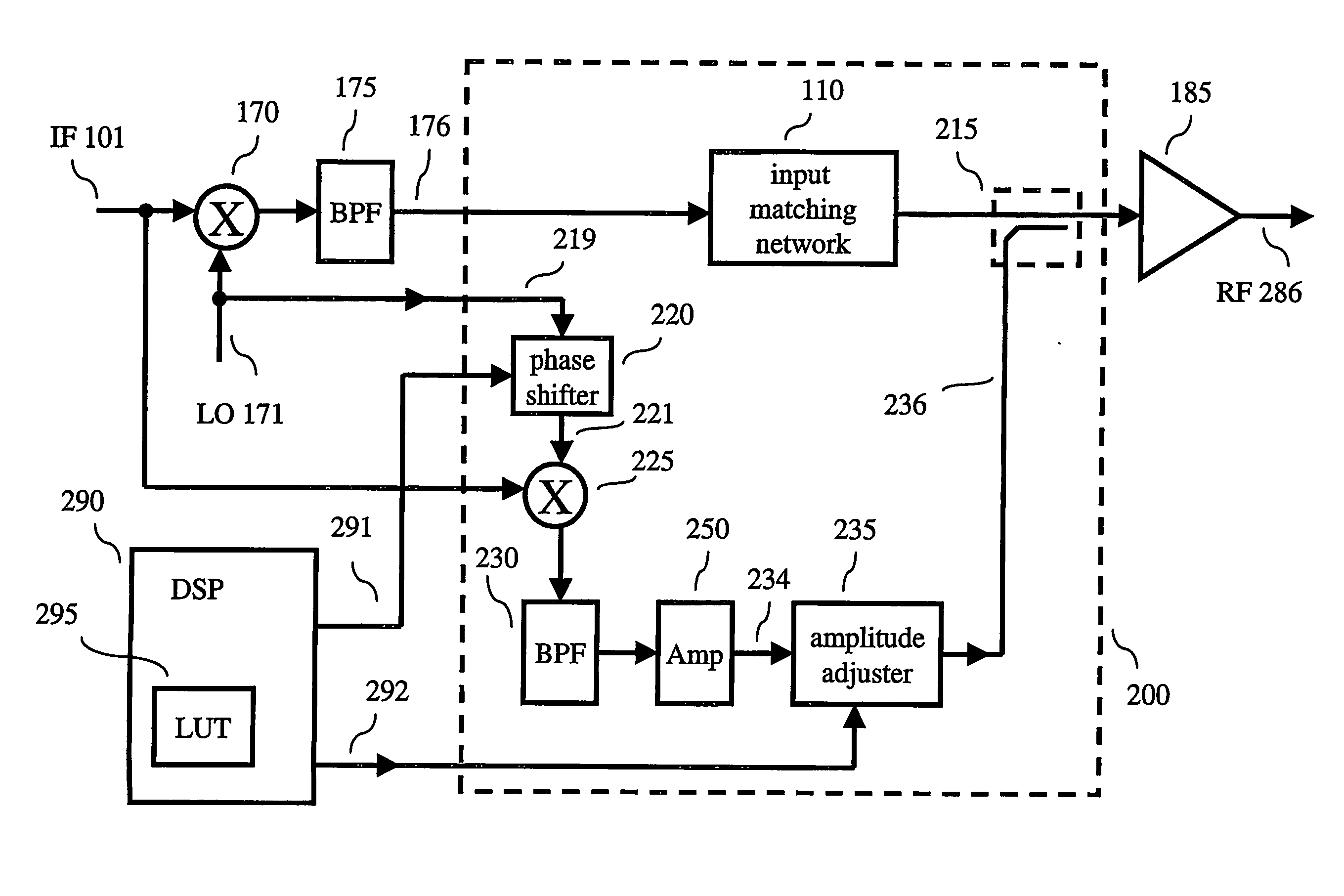
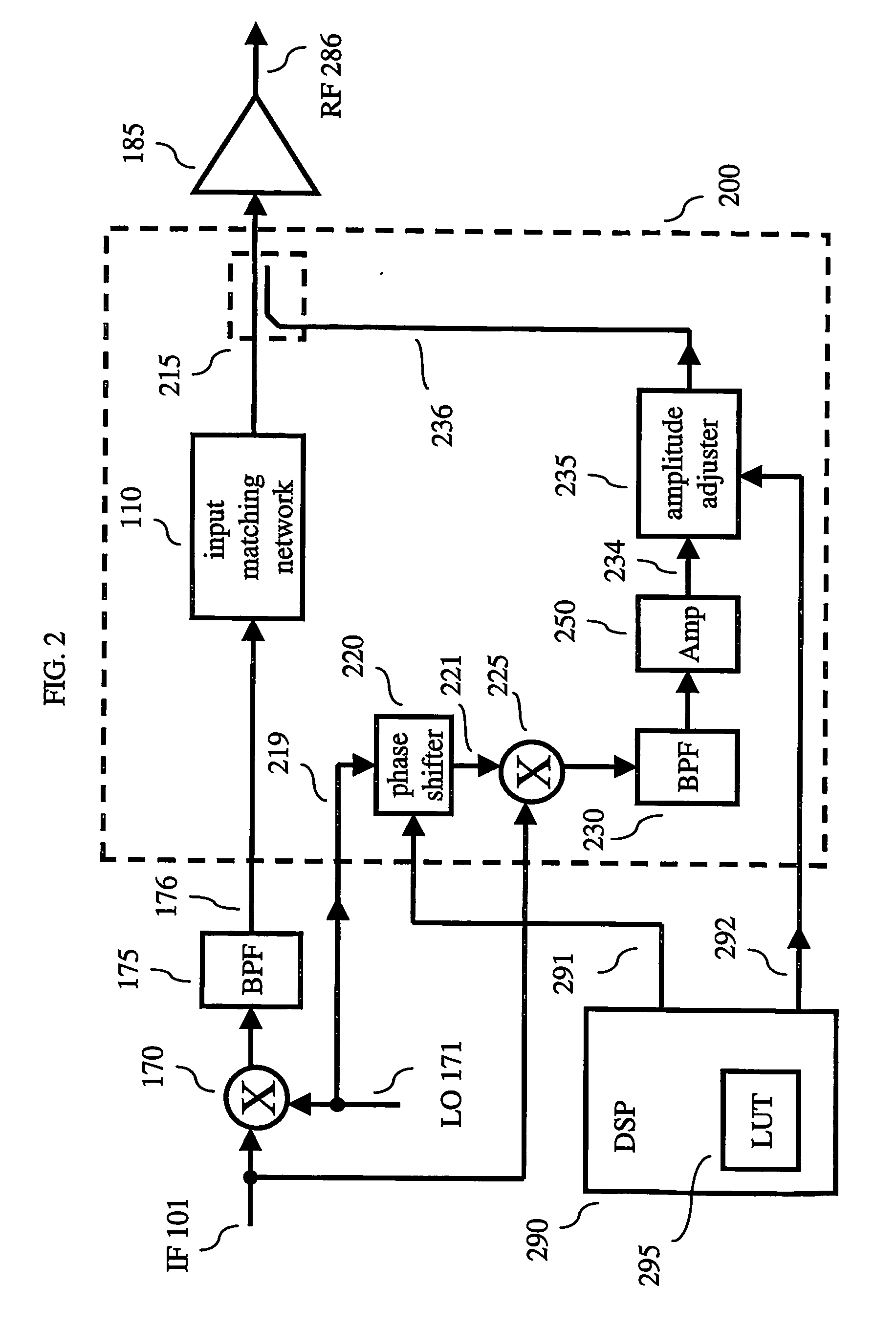
[0006] In view of the above, I have observed that it is possible to lessen at least some of the design requirements for a predistorter for use in a radio frequency (RF) wireless transmitter by operating the phase shifter of the predistorter at less than twice a carrier frequency of the RF transmitter—thus, also lessening the associated cost. Therefore, and in accordance with the principles of the invention, an RF transmitter includes a power amplifier and a predistorter for injecting a distortion signal into an RF signal prior to amplification for use in linearizing the power amplifier; wherein the predistorter includes a phase shifter operating at less than twice a carrier frequency of the RF signal.
[0009] In view of the above, and in accordance with an aspect of the invention, the phase shifter operates at a lower frequency—thus potentially lowering the cost of wireless equipment, fixed or mobile.

Problems solved by technology

Unfortunately, this causes spectral broadening and in-band distortion.
Unfortunately, having to design at twice the operating frequency requirements for components, such as phase shifter 140, further increases their cost and affects the complexity of the overall predistorter implementation.
This imposes more stringent requirements on the permissible level of insertion loss, phase ripple and parasitics with respect to the component inductors, capacitors and varactors that typically comprise the phase shifter—all of which adds to the cost.

Method used


Image

  • Predistorter for use in a wireless transmitter
  • Predistorter for use in a wireless transmitter
  • Predistorter for use in a wireless transmitter

Examples


Embodiment Construction

[0015] Other than the inventive concept, the elements shown in the figures are well known and will not be described in detail. Also, familiarity with wireless communications systems, such as but not limited to UMTS, is assumed and is not described in detail herein. For example, other than the inventive concept, spread spectrum transmission and reception, cells (base stations), user equipment (UE), downlink channels, uplink channels, RAKE receivers, look-up tables and input matching networks are well known and not described herein. In addition, the inventive concept may be implemented using conventional programming techniques, which, as such, will not be described herein. Finally, like-numbers on the figures represent similar elements.

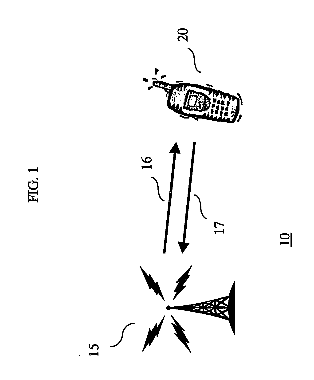
[0016] An illustrative portion of a UMTS wireless communications system 10 in accordance with the principles of the invention is shown in FIG. 1. Cell (or base station) 15 and UMTS User Equipment (UE) 20 communicate therebetween via downlink and uplink...


PUM


Abstract

A wireless radio frequency (RF) transmitter includes a power amplifier and a predistorter for injecting a distortion signal into an RF signal prior to amplification for use in linearizing the power amplifier; wherein the predistorter includes a phase shifter operating at less than twice a carrier frequency of the RF signal.

Description

BACKGROUND OF THE INVENTION [0001] The present invention generally relates to wireless transmitting devices, and more particularly, to techniques for linearization of a power amplifier. [0002] In wireless communications systems, such as the Universal Mobile Telephone System (UMTS), a power amplifier is often driven into the non-linear operating region to increase transmission efficiency. Unfortunately, this causes spectral broadening and in-band distortion. As such, various techniques have been developed to linearize the operation of the transmitter (often referred to as linearization of the power amplifier) while still operating the power amplifier efficiently. [0003] One such technique is predistortion. Generally speaking, in predistortion the signal-to-be-transmitted is first distorted in a complementary fashion to the distortion introduced by the power amplifier. In effect, the distortion introduced into the signal-to-be-transmitted cancels the distortion caused by the non-linea...

Claims


Application Information

Patent Timeline
Patent Type & Authority Applications(United States)
IPC IPC(8): H04B1/04H03F1/32
CPCH03F1/3241H03F1/3247H03F1/3282H03F1/3288H03F2201/3233
Inventor GILBERTON, PHILIPPE
Owner THOMSON LICENSING SA
Learn More