
Ultraviolet light emitting diode systems and methods

a technology of light-emitting diodes and ultra-violet light, which is applied in the field of ultra-violet light-emitting diodes systems and methods, can solve the problems of large ballasts of these lamps, heavy and not portable, and undesirable for the home, and achieves the effects of lamps, and reducing the number of lamps

Inactive Publication Date: 2007-04-19
PHILIPS SOLID STATE LIGHTING SOLUTIONS
View PDF10 Cites 262 Cited by
  • Summary
  • Abstract
  • Description
  • Claims
  • Application Information

AI Technical Summary

Benefits of technology

[0038] Another embodiment of the present invention is directed to a method of impacting the growth of plants. The method may comprise the acts of providing at least one ultraviolet LED, providing at least one visible LED, providing a processor that independently controls the at least one ultraviolet LED and the at least one visible LED, directing the at least one ultraviolet LED and the at least one visible LED to irradiate a plant, and causing the processor to vary the output of the LEDs over a period of time.

Problems solved by technology

There are several problems associated with using high intensity discharge (HID) or low-pressure discharge lamps for the purpose of purifying water.
The ballasts for these lamps are large, heavy and not portable.
With these constraints, the HID source may provide an acceptable solution for industrial settings but is undesirable for the home or as a portable unit.
A problem associated with fluorescent lamps is that the lamps are fragile because they are relatively long tubes of thin glass.
This causes a significant problem in portable units because many of these portable units are used while camping or hiking and the units may not be treated with the care required to prevent breakage.
Another problem associated with the use of either low-pressure or high-pressure discharge tubes for the production of ultraviolet radiation is that both of these sources require a significant amount of mercury to produce the desired radiation.
Mercury is still a significant environmental and health problem.
Another problem associated with shorter wavelength ultraviolet is the dangers to the eyes and skin.
When the shorter wavelengths are used, extra precautions must be used, although long wavelength ultraviolet can also pose concern about eye and skin tissue where there are extended periods of exposure.
If the visible radiation is not filtered out, the film will react to the visible light and the desired effect may not be achieved.
), poor lighting can pose a serious threat to health.
This can lead to many problems ranging from fatigue to depression, even physical ailments.

Method used


Image

  • Ultraviolet light emitting diode systems and methods
  • Ultraviolet light emitting diode systems and methods
  • Ultraviolet light emitting diode systems and methods

Examples


Embodiment Construction

[0046] The description below pertains to several illustrative embodiments of the present invention. Many variations of the invention may be envisioned by one skilled in the art. Such variations and improvements are intended to fall within the compass of this disclosure. Thus, the scope of the invention is not to be limited in any way by the disclosure below.

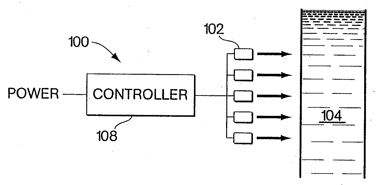
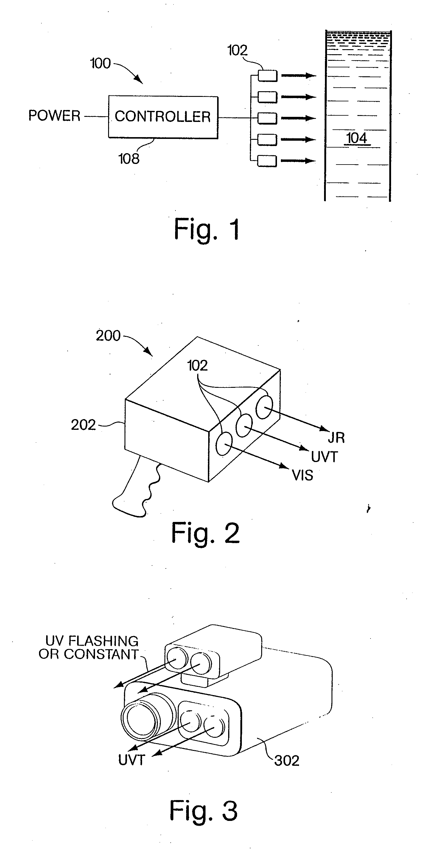
[0047] One embodiment of the invention is directed to the use of ultraviolet radiation, generated light emitting diodes, for purification, inspection and many other uses. This provides a number of advantages over conventional UV sources, including that it is mercury-free.

[0048] The advent of the high brightness light emitting diode (LED) has opened up many new applications for the LED. The LED was primarily used as an indicator light and now is being used as an illumination device. The brightness of the LED has been increasing exponentially over the past three decades. LEDs are now being used in color changing illumination devi...


PUM

PropertyMeasurementUnit
wavelengthaaaaaaaaaa
wavelengthsaaaaaaaaaa

Abstract

Methods and apparatus in which ultraviolet radiation is generated from at least one first LED, an object is irradiated with the ultraviolet radiation, and the ultraviolet radiation is controlled so as to generate at least one perceivable visual effect based on an interaction between the ultraviolet radiation and the object.

Description

CROSS-REFERENCES TO RELATED APPLICATIONS [0001] This application claims the benefit under 35 U.S.C. §120 as a continuation of U.S. non-provisional application Ser. No. 09 / 923,223, filed Aug. 6, 2001, entitled “Ultraviolet Light Emitting Diode Systems and Methods.”[0002] Ser. No. 09 / 923,223 in turn claims the benefit under 35 U.S.C. §119(e) of the following U.S. provisional applications: [0003] Ser. No. 60 / 235,678, filed Sep. 27, 2000, entitled “Ultraviolet Light Emitting Diode Device;” and [0004] Ser. No. 60 / 222,847, filed Aug. 4, 2000, entitled “Ultraviolet Light Emitting Diode Device.”[0005] Ser. No. 09 / 923,223 also claims the benefit under 35 U.S.C. §120 as a continuation-in-part of U.S. non-provisional application Ser. No. 09 / 215,624, filed Dec. 17, 1998, entitled “Smart Light Bulb,” now U.S. Pat. No. 6,528,954, issued Mar. 4, 2003. [0006] Ser. No. 09 / 215,624 in turn claims the benefit under 35 U.S.C. §119(e) of the following U.S. Provisional Applications: [0007] Ser. No. 60 / 071...

Claims


Application Information

Patent Timeline
Patent Type & Authority Applications(United States)
IPC IPC(8): A61L2/04
CPCA01M1/04A61L2/10A61N5/0613A61N2005/0644C02F1/325C02F2201/3222Y02W10/37
Inventor DOWLING, KEVIN J.MORGAN, FREDERICK M.MUELLER, GEORGE G.LYS, IHOR A.TULLMAN, MATTHEW L.
Owner PHILIPS SOLID STATE LIGHTING SOLUTIONS
Learn More