
Method for remote check capture

a remote check and image technology, applied in the field of remote check deposit systems, can solve the problems of relatively expensive depositor sites, introduce software, maintenance and holes, and inefficient and inconvenient for many operators,

Inactive Publication Date: 2007-04-19
PITNEY BOWES INC
View PDF2 Cites 150 Cited by
  • Summary
  • Abstract
  • Description
  • Claims
  • Application Information

AI Technical Summary

Benefits of technology

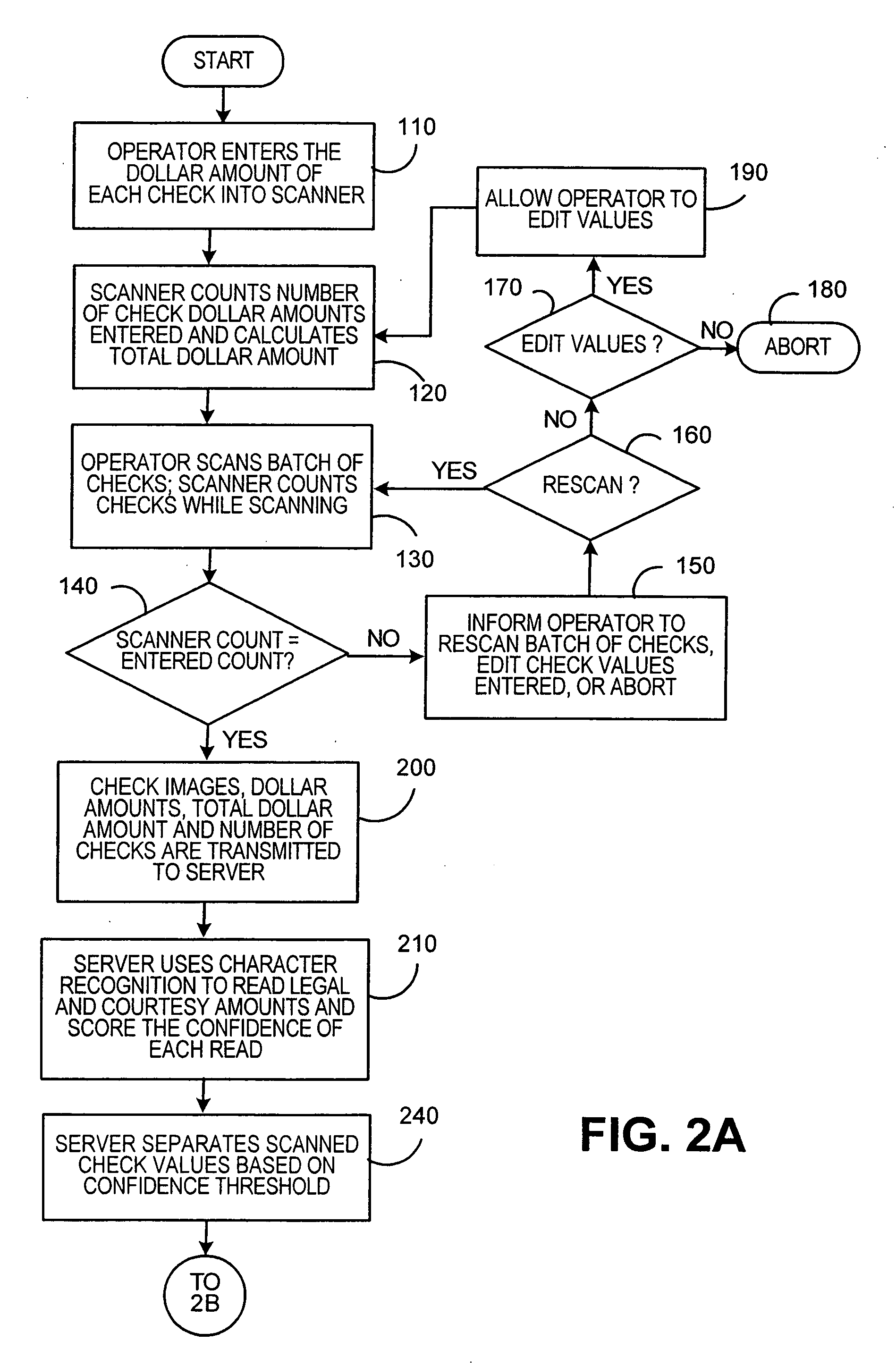
[0005] The present invention relates to a method of enabling the remote deposit of a plurality of checks in a depository bank from a depositor site. The method includes receiving at a second site a plurality of check images and a plurality of entered dollar amounts, wherein the check images were generated at the depositor site by scanning the checks, and wherein each of the entered dollar amounts were entered at the depositor site. In addition, each of the entered dollar amounts correspond to a respective one of the check images. The method further includes using character recognition at the second site to read a first recognized dollar amount from each of the check images and assign a confidence level to each of the first recognized dollar amounts. The check images are then divided into a high confidence group and a low confidence group, wherein each of the check images in the high confidence group have a confidence level corresponding thereto that is greater than or equal to a predetermined level, and each of the check images in the low confidence group have a confidence level corresponding thereto that is less

Problems solved by technology

While such systems add convenience for depositors and reduce the amount of, and thus the cost of, bank operator intervention, they require PCs and software at the depositor site that are relatively expensive and that introduce problems associated with software, maintenance and holes.
This device, however, requires that checks be scanned and information related thereto be entered one at a time, which may prove inefficient and inconvenient for many operators.
As will be appreciated, such a solution, while effective, increases the frequency at which bank personnel must be involved in the check deposit process, which adds expense and consumes bank resources.

Method used


Image

  • Method for remote check capture
  • Method for remote check capture
  • Method for remote check capture

Examples


Embodiment Construction

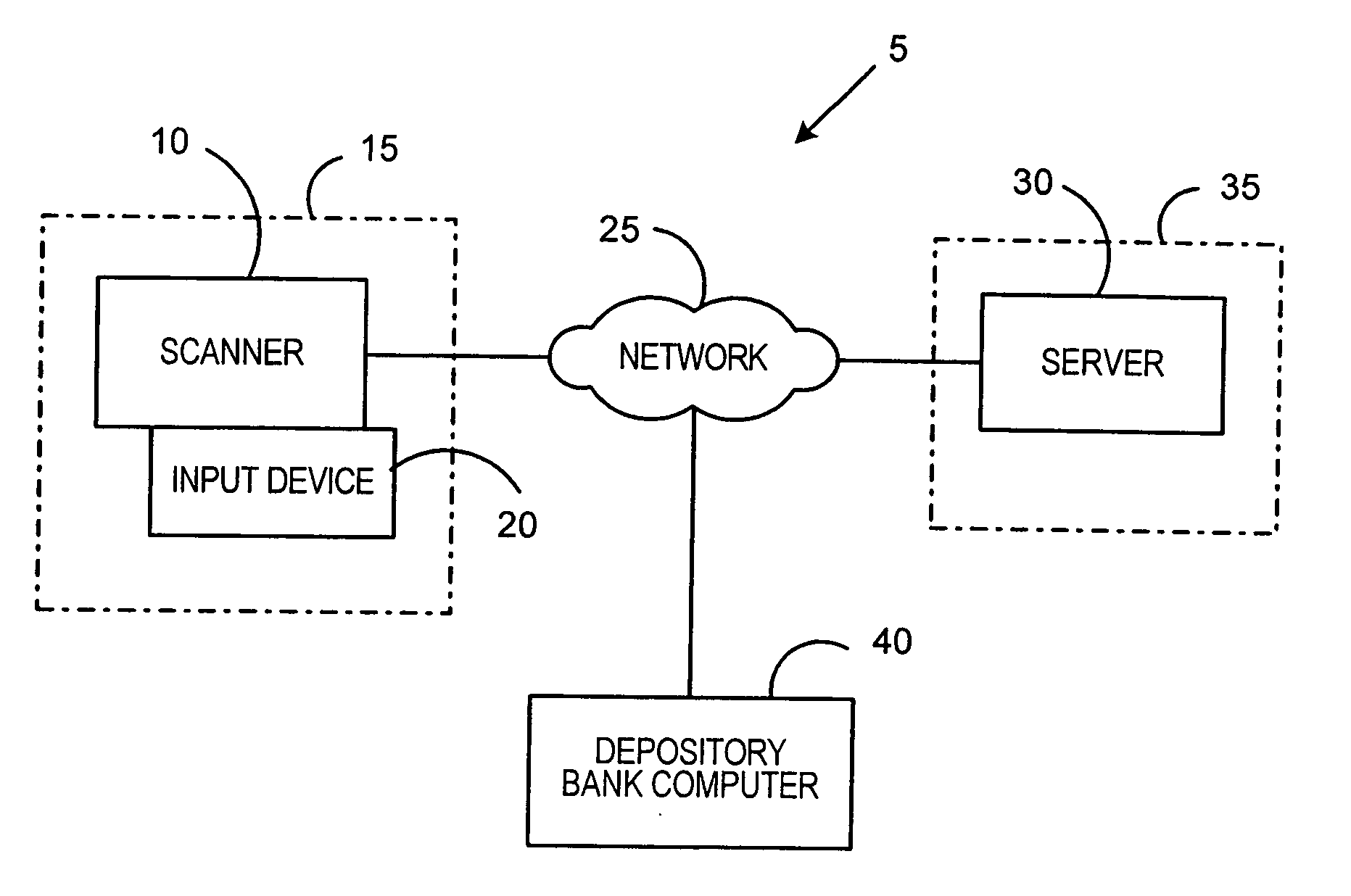
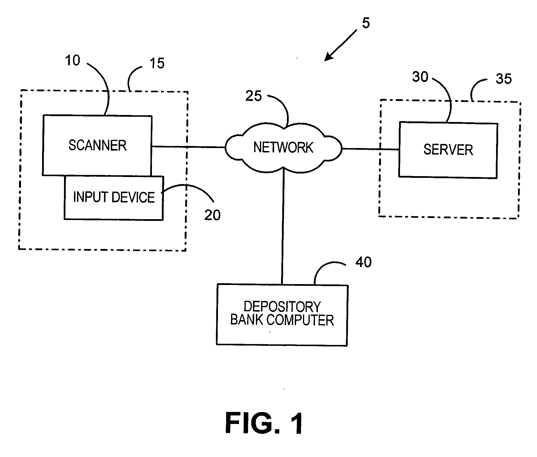
[0014]FIG. 1 is a block diagram of a remote check capture system 5 according to the present invention. Remote check capture system 5 enables a depositor to remotely deposit a number of checks in a particular depository bank. Remote check capture system 5 includes a digital scanner 10 located at a depositor location 15 for scanning and thereby creating electronic images of the checks to be deposited. The digital scanner 10 includes an input device 20 that enables an operator of the digital scanner 10, such as an accounts receivable clerk, to input information, as described herein, into the digital scanner 10. The input device 20 may be, for example, a keypad, a keyboard, a touch screen or the like provided as part of the digital scanner 10. The digital scanner 10 also includes a processing unit (not shown), such as a microprocessor, and a memory (not shown), which may be any of a variety of types of internal and / or external storage media such as, without limitation, RAM, ROM, EPROM(s...


PUM


Abstract

A method of enabling remote deposit of checks includes receiving at a second site a plurality of check images and a plurality of entered dollar amounts, wherein the check images were generated at the depositor site by scanning the checks and the entered dollar amounts were manually entered at the depositor site. Each of the entered dollar amounts correspond to a respective one of the check images. The check dollar amounts are read from the check images at the second site using character recognition, and certain of the entered dollar amounts are used as hints to improve the accuracy of the character recognition. The enhanced character recognition results are provided to the depository bank along with the check images to enable the checks to be deposited in the depositor's account.

Description

FIELD OF THE INVENTION [0001] The present invention relates to check deposit systems, and in particular to a method for remote check image capture and deposit. BACKGROUND OF THE INVENTION [0002] Traditionally, businesses have deposited checks received from, for example, customers by physically taking them to a branch of their bank and depositing them over the counter with a teller or dropping them into a night deposit box. The actual physical presentation of checks to be deposited was necessary because, under prior banking laws, the depository bank had to present the original of each check to the corresponding paying bank in order to clear the check. This changed in October of 2004 with the enactment of The Check Clearing for the 21st Century Act, commonly referred to Check 21. Check 21 removed the legal requirement that an original paper check had to be presented to obtain payment. Instead, banks can now use digital images to transport check data from the bank of first deposit to t...

Claims


Application Information

Patent Timeline
IPC IPC(8): G06K9/00
CPCG06K9/033G06Q20/042G06V10/987
Inventor FOTH, THOMAS J.PIERCE, JEFFREY D.CAREY-STECKBAUER, HILLARY
Owner PITNEY BOWES INC
Learn More