
Product de-topper

a technology for stacked products and packaging, applied in the directions of dough processing, application, transportation and packaging, etc., can solve the problems of increasing maintenance costs, requiring complex disassembly and cleaning procedures, and undesirable food production downtime, and achieve the effect of facilitating the desired parting or separation of stacked products

Inactive Publication Date: 2007-04-19
AUBRY LARRY +2
View PDF34 Cites 6 Cited by
  • Summary
  • Abstract
  • Description
  • Claims
  • Application Information

AI Technical Summary

Benefits of technology

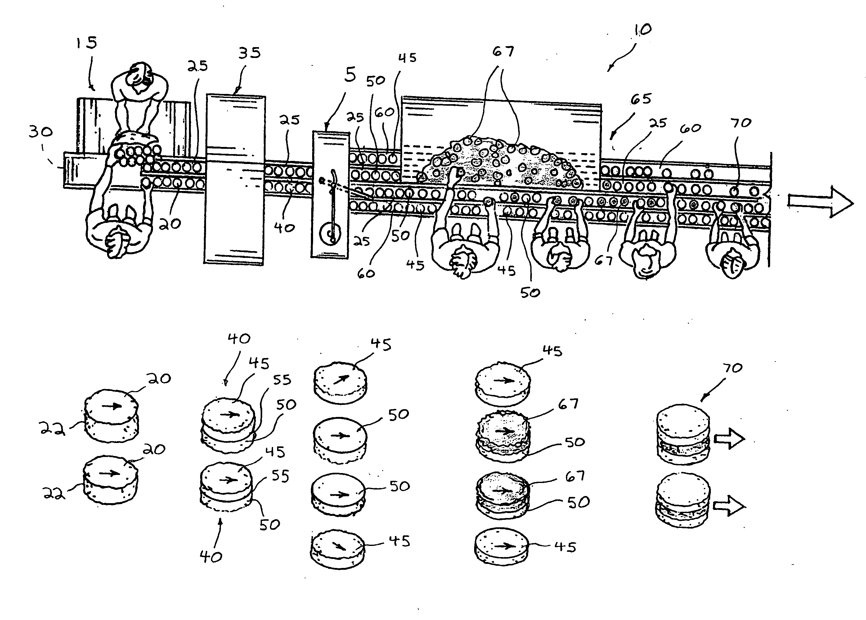
[0011] The present invention relates to equipment for assembling food products, and more specifically to an apparatus and method for separating or parting stacked food products during a food production process. The invention, a de-topper, facilitates the desired parting or separation of stacked products along a separation line defining an elevation. For ease of description, the example of sliced, stacked biscuit food products will be used in describing the de-topper, but it is understood that any possible stackable food or non-food product can also be parted or separated by the de-topper as well.
[0020] The location of the inner barriers along the primary paths to define-the secondary paths also defines the width of the primary paths. The placement of the inner barriers thus establishes a predetermined width of the primary paths such that each path preferably accommodates the width of one biscuit thereon, with the paths accommodating a plurality of biscuits preferably in “single-file” formation. To define the widths of the secondary paths, at least one outer barrier can be located there-along to preferably accommodate the width of a single biscuit as well. The at least one outer barrier prevents the upper section of the biscuit deposited on the at least one secondary path from moving further transversely from and off of the path.

Problems solved by technology

Although “de-topper” mechanisms or assemblies are present in the art for parting stacked products such as bun or biscuit sections, numerous disadvantages are associated with these de-toppers.
Transverses conveyors, however, have a conveyor belt and related components that are prone to contamination, thus requiring complex disassembly and cleaning procedures in compliance with government food production sanitary standards.
Such complex disassembly and cleaning procedures of such transverse conveyors thus result in undesirable food production down-time and increased maintenance costs.
Furthermore, the transverse conveyor is not readily adjustable in relation to the conveying path of the stacked bun or biscuit sections to allow for an adjustment of the angle of the transverse conveyor in relation to the conveying path.
However, such pivoted lever arms suffer the disadvantage of placing each upper bun or biscuit section rearwardly of each lower section on a common conveying path, instead of placing the upper sections onto a conveying path separate from that of the lower sections.
Such a placement of each upper section rearwardly of each lower section on a common conveying path results in counter-productive confusion during any sandwich assembly process requiring that the top section of the bun or biscuit be replaced on top of the lower section and remaining sandwich components (i.e. on top of the bun or biscuit bottom section having meat, cheese or other products located thereon).
The confusion results when assembly personnel have difficulty differentiating between the bun or biscuit upper and lower sections, due to their location on the common pathway, thus resulting in improperly-assembled sandwiches having the bottom section placed on top of the remaining sandwich components and / or the top section placed at the bottom of the sandwich.

Method used


Image

  • Product de-topper
  • Product de-topper
  • Product de-topper

Examples


Embodiment Construction

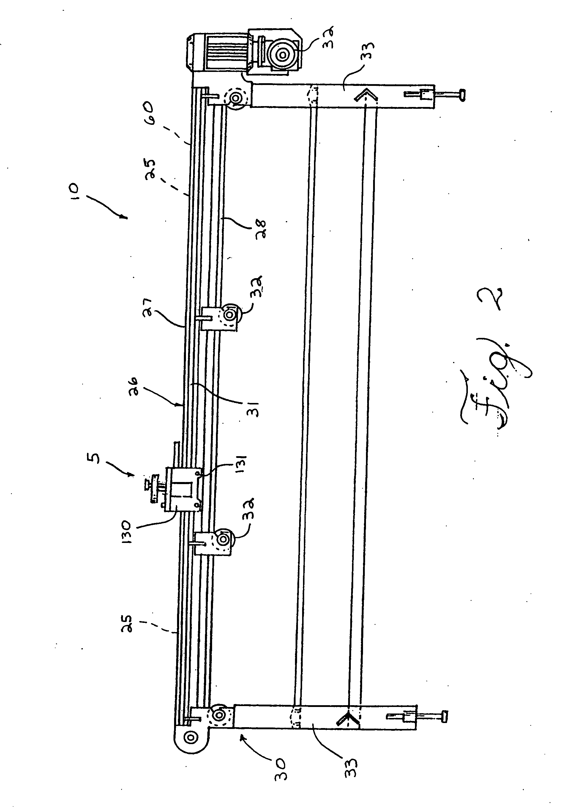
[0033] The present invention relates to equipment for assembling food products, and more specifically to an apparatus and method for separating or parting stacked food products during a food production process. The invention, a de-topper, facilitates the desired parting or separation of stacked products along a separation line defining an elevation. For ease of description, the example of sliced, stacked biscuit food products will be used in describing the de-topper, but it is understood that any possible stackable food or non-food product can also be parted or separated by the de-topper as well. FIG. 1 illustrates a plan view of one embodiment of the de-topper 5 as part of a food product production line 10, along with a perspective view of the biscuit food product after each step of the production process. As illustrated in FIG. 1, the line preferably assembles breakfast sandwiches from individual sandwich components comprising sliced biscuits or other breads, meats, cheeses, cooke...


PUM


Abstract

The present invention relates to equipment for assembling food products, and more specifically to an apparatus and method for separating or parting stacked food products during a food production process. The invention, a de-topper, facilitates the desired parting or separation of stacked products having at least upper and lower sections defining a separation line. In parting stacked products along the separation line, the de-topper comprises a longitudinal arm and at least one primary conveying path for conveying the at least upper and lower sections of the stacked products towards the arm. A drive reciprocates the arm so that the reciprocating arm sweeps the upper sections of the stacked products from the at least one primary conveying path and onto a secondary conveying path, located outwardly thereof. The lower and upper sections are thereafter conveyed on the respective primary and secondary conveying paths away from the reciprocating longitudinal arm.

Description

CROSS REFERENCE TO RELATED APPLICATIONS [0001] This application claims priority to U.S. Provisional Patent Application Ser. No. 60 / 726,906 filed on Oct. 14, 2005.TECHNICAL FIELD OF THE INVENTION [0002] The present invention relates to equipment for assembling food products, and more specifically to an apparatus and method for separating or parting stacked food products. BACKGROUND OF THE INVENTION [0003] During the production and assembly of food products, various food components are processed and assembled along a conveying path into a final food product. For example, buns or biscuits may be sliced into at least upper and lower sections and then assembled with meat, cheese of other product slices or pieces between the upper and lower sections to make a sandwich. [0004] To cut a bun or biscuit into the at least upper and lower sections, a whole bun or biscuit typically is conveyed along a conveying path (i.e. conveyor belt) and travels through and past a longitudinal band-saw locate...

Claims


Application Information

Patent Timeline
IPC IPC(8): B65G47/26
CPCA21C9/086A21C15/02
Inventor AUBRY, LARRYZABALA, JOEGRUDZIEN, ARKADIUSZ
Owner AUBRY LARRY
Learn More