
Method for the production of a leadthrough in a fibre compound material, as well as a rotor blade for a wind energy facility with a leadthrough

a technology of compound material and rotor blade, which is applied in the direction of motors, applications, domestic articles, etc., can solve the problems of opening in the half-finished fibre product, and achieve the effect of avoiding any weakening of the fibre compound material

Inactive Publication Date: 2007-04-12
NORDEX ENERGY
View PDF2 Cites 47 Cited by
  • Summary
  • Abstract
  • Description
  • Claims
  • Application Information

AI Technical Summary

Benefits of technology

[0007] The present invention is based on the technical goal to provide a leadthrough in a roto

Problems solved by technology

Thus, the opening in the half-finished fibre product is not made by punching out,

Method used


Image

  • Method for the production of a leadthrough in a fibre compound material, as well as a rotor blade for a wind energy facility with a leadthrough
  • Method for the production of a leadthrough in a fibre compound material, as well as a rotor blade for a wind energy facility with a leadthrough
  • Method for the production of a leadthrough in a fibre compound material, as well as a rotor blade for a wind energy facility with a leadthrough

Examples


Embodiment Construction

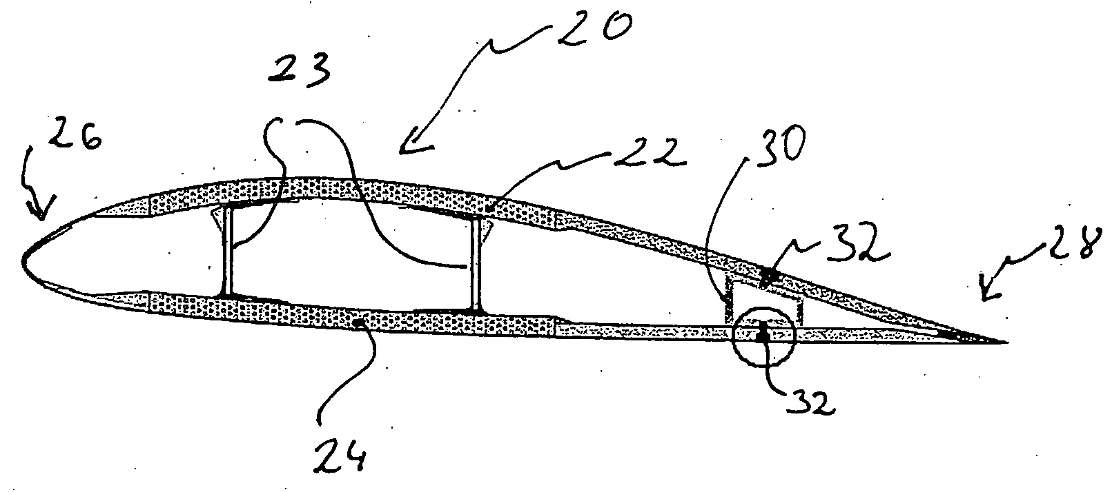
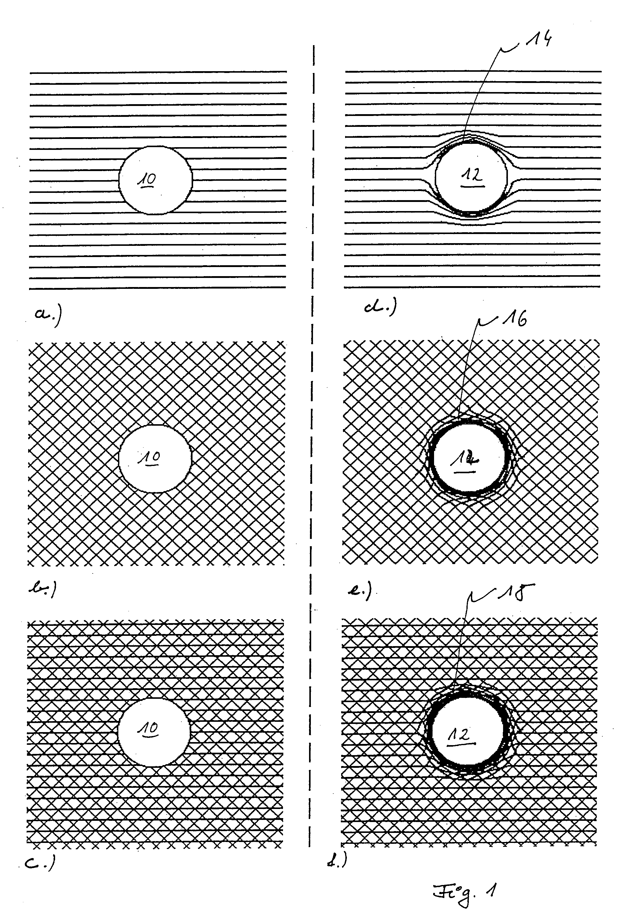
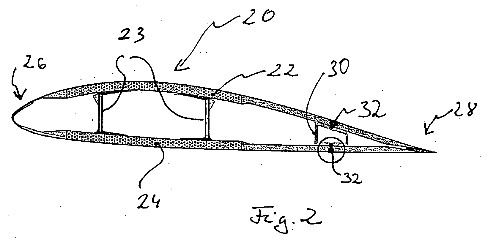
[0018] While this invention may be embodied in many different forms, there are described in detail herein a specific preferred embodiment of the invention. This description is an exemplification of the principles of the invention and is not intended to limit the invention to the particular embodiment illustrated FIG. 1 shows on its left side different fibre tissues, the fibres of which were interrupted by the belated making of a leadthrough 10.

[0019]FIG. 1a shows a unidirectional (UD) course of the fibres, in which the fibres run substantially parallel. FIG. 1b shows a biaxial arrangement, in which the fibres run in two preferential directions, which are vertical with respect to each other. FIG. 1c shows a triaxial orientation of the fibres, in which the fibres run in three directions. It is common to all the three orientations of the fibres that the fibres in the wall of the hole are interrupted by the leadthrough 10. Therefore, the interrupted fibres can no more take up the force...


PUM

PropertyMeasurementUnit
Electrical conductivityaaaaaaaaaa
Perimeteraaaaaaaaaa

Abstract

A method for the production of a leadthrough in a fibre compound material for a rotor blade, with the following procedure steps: an opening free of fibres (12) is provided in a half-finished fibre product such that the fibres run around the opening (12), the half-finished fibre product is processed into a fibre compound material by adding a matrix material, and the leadthrough is put in place through the opening in the half-finished fibre product.

Description

CROSS-REFERENCE TO RELATED APPLICATIONS [0001] Not applicable. STATEMENT REGARDING FEDERALLY SPONSORED RESEARCH [0002] Not applicable. BACKGROUND OF THE INVENTION [0003] The present invention is related to a method for the production of a leadthrough in a fibre compound material for a rotor blade. It is also related to a rotor blade for a wind energy facility with a leadthrough through a rotor blade wall. [0004] A leadthrough in the rotor blade wall serves as a through hole for the installation of component parts, for instance, which extend from the interior of the rotor blade through the shell towards the outside. Such component parts are receptors for the lightning protection of the wind energy facility, cross bolts for fixing the rotor blade, means for indicating danger, sensors and draining equipments, for instance. Yet, the leadthrough in the rotor blade wall can also serve as an access opening for putting in place or removal of objects like trimming weights, for instance, or i...

Claims


Application Information

Patent Timeline
IPC IPC(8): B64C27/46
CPCF03D1/065F03D11/0033Y02E10/721Y02E10/722B29C70/545B29C2793/0081B29L2031/085F03D80/30Y02E10/72Y02P70/50
Inventor NIES, DANIEL
Owner NORDEX ENERGY
Learn More