Apparatus and method for preparing optical fiber preform having desired cone shape

Inactive Publication Date: 2007-04-12
STERLITE TECHNOLOGIES
View PDF11 Cites 2 Cited by
  • Summary
  • Abstract
  • Description
  • Claims
  • Application Information

AI Technical Summary

Benefits of technology

[0020] Accordingly, the main object of the present invention is to provide a method and an apparatus for preparing desired cone shape of the preform, wherein no step of heating of preform end is performed meaning thereby which overcomes all associated disadvantages, drawbacks and limitations of the step of heating the preform end as described herein, and hence of cooling the preform end after preparation of preform cone, and which also addresses the problems encountered during the process step of cone preparation just before the process step of fiber draw and which is also suitable to produce preform cone having precisely controlled cone of desired shape and dimensions, including desired diameter suitable for start of fiber draw without wastage of preform.
[0021] One particular object of the present invention is to provide a method and an apparatus for preparing desired cone shape of the preform, wherein step of heating the preform end to a very high temperature of about 2000° C. is totally avoided / eliminated to finally have a preform cone of desired shape, which is not only suitable for start of fiber draw step to finally draw the fiber but also avoids formation of any defects in the preform cone to avoid possibility of breakage meaning thereby reduces the loss of fiber length during start of fiber draw step results in exorbitant power and energy savings.
[0022] Another particular object of the present invention is to provide a method and an apparatus for preparing desired cone shape of the preform, wherein the preform cone having any desired shape and dimensions, including higher diameter can be prepared with ease and convenience and within a short span of time meaning thereby making the overall process not only controlled and convenient, but also highly time saving, and hence, making the overall process highly productive and economical for commercial applications.

Problems solved by technology

However, the IPA1073 method does not address the problems encountered during the process step of cone preparation just before the step of fiber draw.
Accordingly, in accordance with methods as known in the prior art, the fiber draw step is performed while heating the preform end to a very high temperature of about 2000° C. However, desired shape of cone formation in drawing stage before the fiber draw step consumes more than one hour for each preform, which will reduce the productivity of optical fiber.
The main problem of preparation of cone having desired shape which is suitable for start of fiber draw step at one of the opposite ends of the preform by heating the respective opposite end is that the preform bottom end needs to be loaded in a specially built furnace to heat the preform to a very high temperature of the order of about 2000° C. Further, if the cone is prepared at one of the preform ends by step of heating and such preform is required to be stored before drawing the fiber, then the preform is required to be cooled to a temperature suitable for safe handling and storage, which can only be achieved by loading the preform from the step of heating in a specially built containers or vessels comprising proper cooling systems for the step of cooling.
Therefore, the known methods of preparing the cone of desired shape by heating not only suffer from the drawbacks of requiring a step of heating the preform in a specially built furnace to a very high temperature of the order of about 2000° C. and requiring specially built containers or vessels comprising proper cooling systems for loading of preform for the step of cooling, that is also suffer from the problem of requiring additional process step of cooling the preform after preparation of cone of desired shape if the preform has to be stored for fiber draw at a later stage.
Further, it has been observed that the cooling of the preform has to be performed very carefully in a highly controlled manner, because non-uniform cooling or immediate cooling or abrupt cooling has been shown to cause physical defects and stress formation in the preform cone.
It has been observed that physical defects and stress in the preform cone leads to transmission loss in the resulting optical fiber or distort other optical parameters, for example, polarization mode dispersion, cutoff wavelength etc.
Therefore, the known processes for preparation of cone of desired shape just before the fiber draw step are not only highly time consuming and power or energy consuming, but are also highly complicated and uneconomical for commercial applications, because of requirement of specially built furnaces with specially designed heating means for example burners of hydroxyl flame, heating by graphite resistance or induction furnace, or by plasma heating means, power full heating means of laser, like carbon dioxide laser etc. for heating the preform end and requirement of specially designed containers or vessels comprising proper cooling systems for loading of preform to have cooling in highly controlled manner.
The hydroxyl flame which is commonly used for cone preparation has been observed to result in increase of hydroxyl contents of the preform, which in-turn has been observed to result in increased transmission loss, particularly at about 1380 nm wavelength band meaning thereby the preform is not suitable for CDWM (16 Channels) applications.
Further, the use of commonly used hydroxyl flame also results in wastage of the glass during the cone cutting process.
The heating by graphite resistance or induction furnace has been observed to cause graphite oxidation which results in formation of oxidation products, for example ash, graphite particles etc. which adheres to the preform surface, and such contamination of the preform with unwanted particles results in production of a preform which will produce a fiber having transmission loss and poor strength.
Further drawback of the preform cone preparation by heating step is that the preform has to be placed inside the furnace, the gap between the furnace and preform needs to be sealed properly, otherwise the graphite heating material will get oxidized thus particles will adhere to the outer surface of preform and / or cone.
The lasers, such as carbon dioxide lasers, which are clean heat source to operate, also suffer from the drawback of consuming high power to generate required high temperature meaning thereby there is increase in overall production cost.
Further, with use of lasers, one cannot produce preform cones of higher diameter.
Further, it has also been observed that large amount of thermal induced stress in the preform cone area may shatter the preform to pieces.
It has been further observed that whatever, one may do to have controlled heating and controlled cooling, even then by the known methods of preparation of the preform cone by step of heating followed by step of cooling, one cannot have precisely controlled cone of desired shape and dimensions which can be suitable for start of fiber draw without wastage of preform meaning thereby one cannot have preform cone of predetermined shape and dimensions including desired diameter.

Method used


Image

  • Apparatus and method for preparing optical fiber preform having desired cone shape
  • Apparatus and method for preparing optical fiber preform having desired cone shape
  • Apparatus and method for preparing optical fiber preform having desired cone shape

Examples


Embodiment Construction

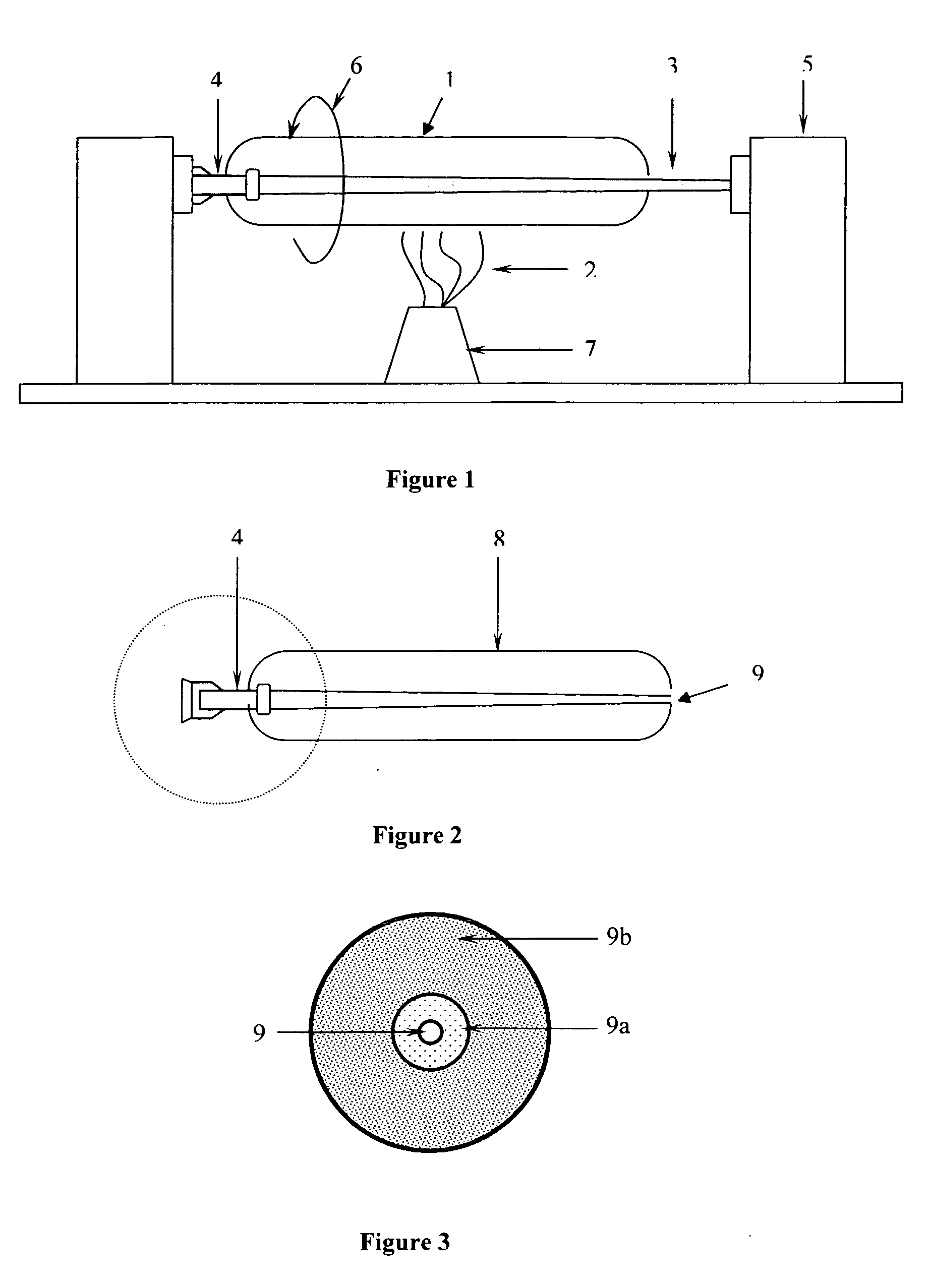
[0047] The soot porous body can be prepared by any method known in the art. For example, by atmospheric chemical vapour deposition [ACVD] method. In accordance with a typical process to manufacture a preform, as for example illustrated in accompanying FIG. 1, the preparation of soot porous body 1 comprises the following steps. The glass-forming precursor compounds are oxidized and hydrolyzed to form porous silica based materials 2. The porous silica based materials 2 are deposited on a tapered cylindrical member referred as mandrel 3, which can be any commercially available mandrel with or without any specific preparation, preferably with specific preparation to remove the contaminants therefrom which is provided with a handle rod 4 and fitted on a lathe 5 to form soot porous body 1.

[0048] During the step of deposition, the mandrel 3 is rotated in a direction as illustrated by an arrow 6 and also moved along its length with reference to burner 7 to deposit the soot particles 2 on t...


PUM

PropertyMeasurementUnit
Nanoscale particle sizeaaaaaaaaaa
Temperatureaaaaaaaaaa
Diameteraaaaaaaaaa

Abstract

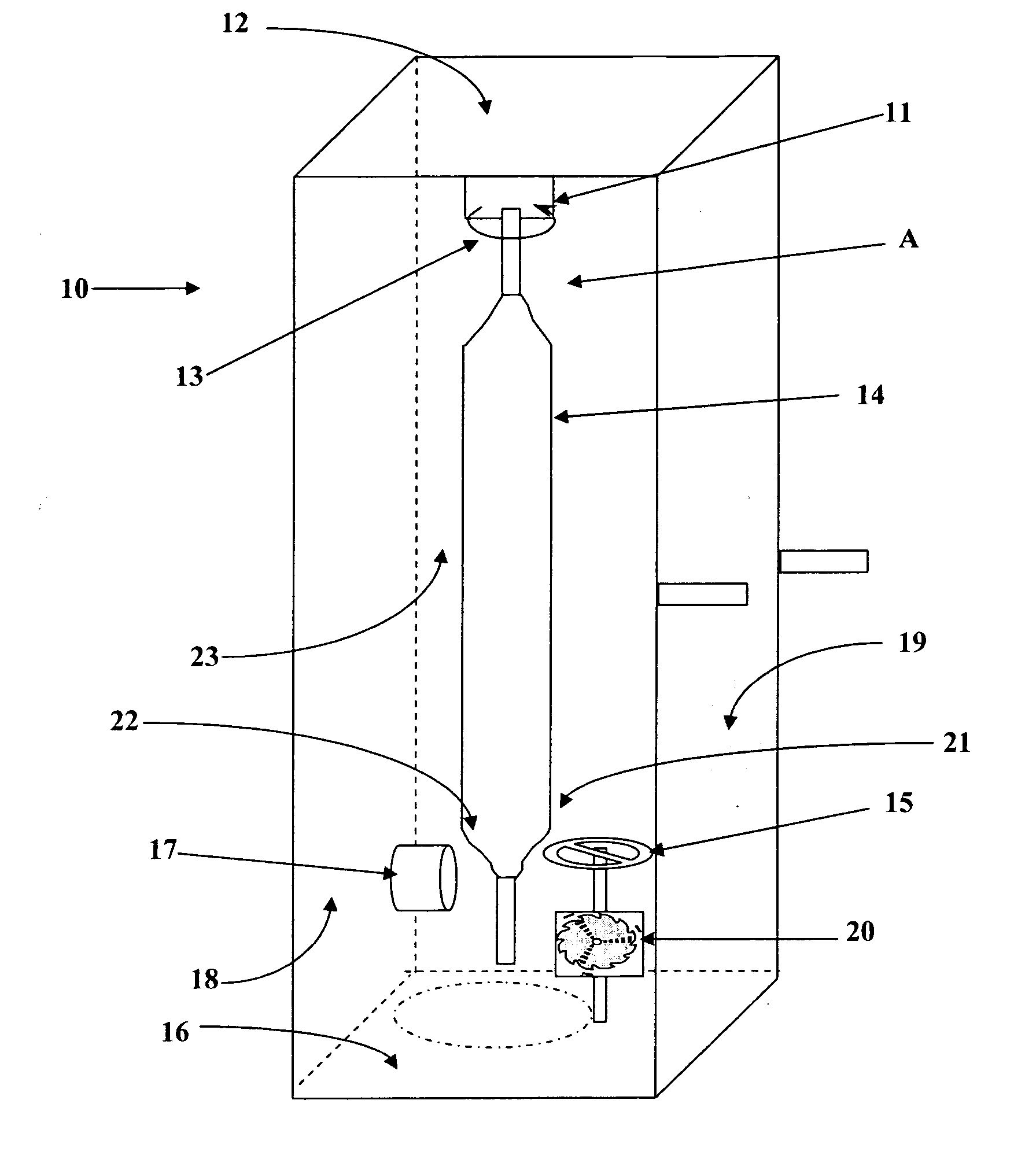
An apparatus for preparing a preform cone having desired shape and dimensions, including diameter is provided, wherein said apparatus comprises a box type structure having a coupling means suitably provided on the inner side of upper face for holding one end of the core rod of the soot preform which is required to be subjected to step of cone preparation; a grinding or cutting means suitably provided on the inner side of one of the faces of the box type structure for grinding or cutting the preform end to produce preform cone of desired shape and dimensions including diameter; a suction means suitably provided on inner side of one of the faces of the box type structure for immediate removal of soot particles produced during grinding or cutting of the preform end to produce the preform cone of desired shape and dimensions; and an adjustable rotating means suitably connectable to grinding or cutting means to have simultaneous control of rotation speed and position of the grinding or cutting means with respect to preform end wherein the preform cone is being prepared. A process for preparation of preform cone of desired shape and dimensions including diameter, and soot preform prepared by said process and optical fiber prepared from said soot preform are also provided.

Description

FIELD OF THE INVENTION [0001] The present invention relates to an apparatus and method for preparing optical fiber preform having desired cone shape. Particularly, it relates to an apparatus and method for preparing a cone of the preform so as to make it suitable for drawing the fiber and at the same time saving wastage of ends of the preform, and process time and process energy to make the overall process highly convenient and economical. The present invention also relates to optical fiber preform produced while employing apparatus and method of the present invention, and to the fiber produced from such preform. BACKGROUND OF THE INVENTION [0002] Optical fibers are inherently versatile as a transmission medium for all forms of information, be it voice, video or data. The optical fibers are drawn from an optical fiber preform. The optical fiber of predetermined dimension is drawn from the optical fiber preform by subjecting one end of the preform to a high temperature, for example a...

Claims


Application Information

Patent Timeline
IPC IPC(8): C03B37/16C03B37/018
CPCC03B37/01466Y02P40/57
Inventor KULKARNI, PARAGNAGARKAR, SHAM
Owner STERLITE TECHNOLOGIES
Why Eureka
Try Eureka