
Wireless base station and wireless communication system

a wireless communication system and wireless base station technology, applied in wireless communication, electrical equipment, selection arrangements, etc., can solve the problems of data frame collision, reduced throughput in the whole network, and not always installed in all wireless base stations and terminals, so as to prevent frame collisions between wireless terminal stations, prevent frame collisions and traffic control, and achieve high-reliability wireless communication. , the effect of high reliability

Inactive Publication Date: 2007-04-05
MITSUBISHI ELECTRIC CORP
View PDF3 Cites 41 Cited by
  • Summary
  • Abstract
  • Description
  • Claims
  • Application Information

AI Technical Summary

Benefits of technology

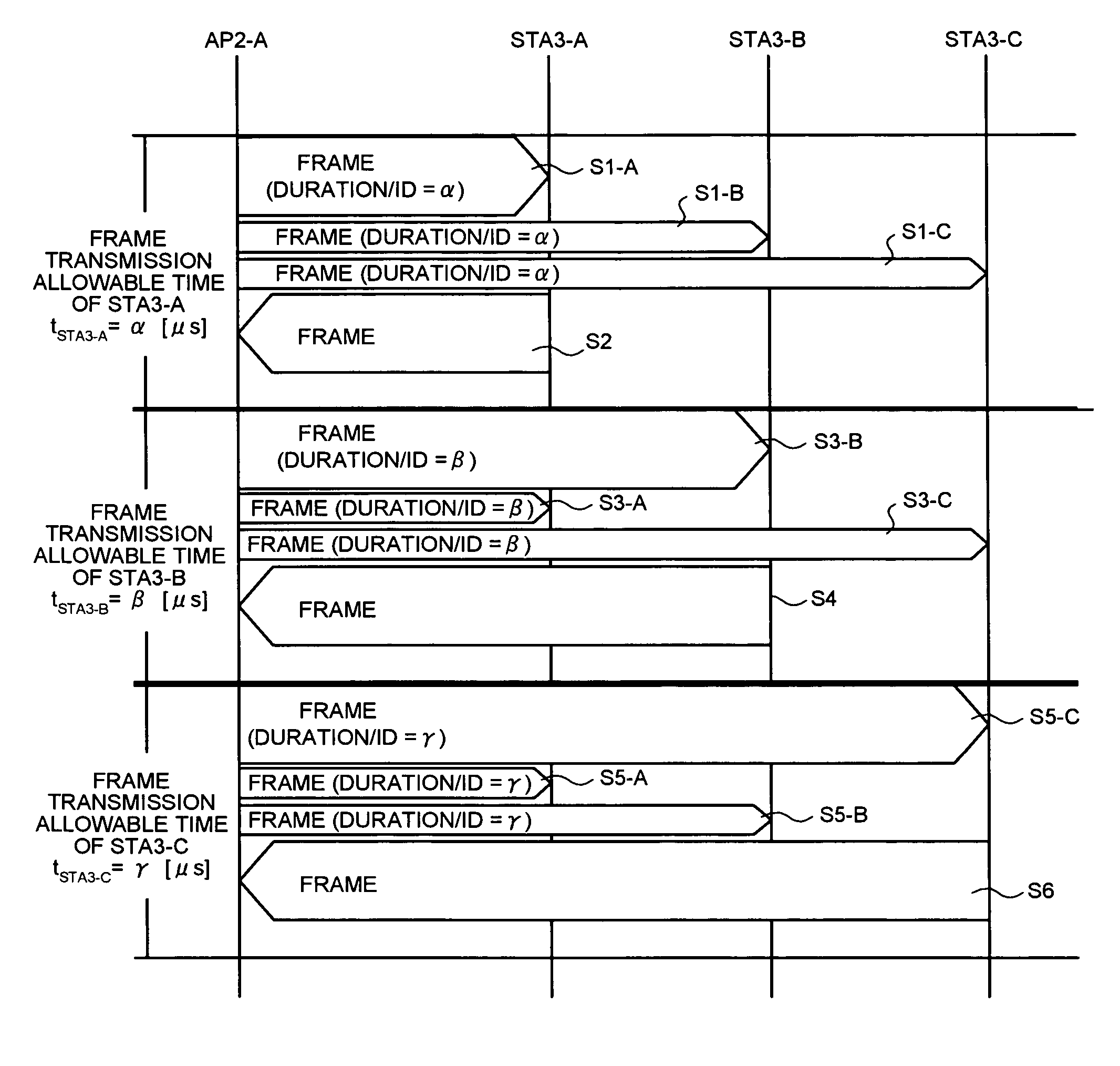
[0020] Accordingly, frame transmission between the wireless terminal stations can be controlled, and frame collisions between the wireless terminal stations can be prevented reliably. According to the present invention, therefore, in the wireless communication system in conformity with the IEEE 802.11a, b, and g, prevention of frame collisions and traffic control between the wireless terminal stations are realized, thereby realizing highly reliable wireless communications.

Problems solved by technology

In this case, however, a collision of data frames occurs.
However, in the IEEE 802.11, since the integrated control is an optional function, it is not always installed in all wireless base stations and terminals.
When the wireless base stations are arranged in a high density, or when the terminals are overcrowded, the probability of the occurrence of this phenomenon increases, thereby causing a problem in that the throughput in the whole network decreases.
However, since not all the wireless base stations and the terminals support the PCF method, when there is a terminal which only supports the PCF method, the same problem as in the DCF method occurs.
In Patent document 1, while a collision prevention method after a collision has occurred is disclosed, the occurrence of frame collisions cannot be reduced when frame transmission is started at the same timing, which is the basic problem.
However, the same problem as in the PCF method will occur, unless all the wireless base stations and wireless terminal stations support the PCF method.

Method used


Image

  • Wireless base station and wireless communication system
  • Wireless base station and wireless communication system
  • Wireless base station and wireless communication system

Examples


first embodiment

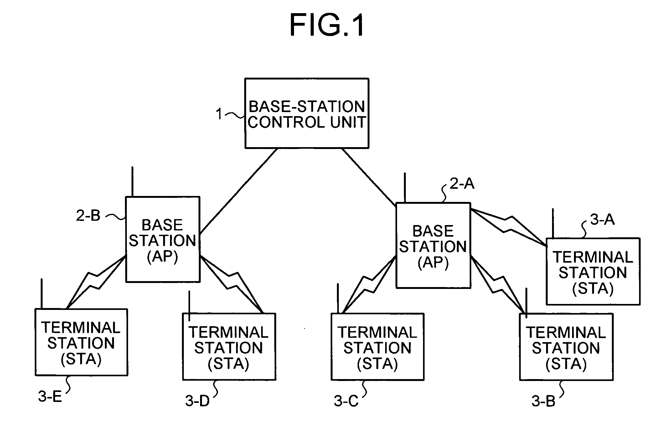
[0033]FIG. 1 depicts the configuration of a wireless communication system according to a first embodiment of the present invention. As shown in FIG. 1, the wireless communication system according to the first embodiment is a wireless LAN system in conformity with the IEEE 802.11a, b, and g, including a wireless base-station control unit 1, wireless base stations (AP) 2-A, 2-B (hereinafter, also referred to as wireless base station (AP) 2), and wireless terminal stations (STA) 3-A, 3-B, 3-C, 3-D, and 3-E (hereinafter, also referred to as wireless terminal station (STA) 3). The wireless communication system adopts the Distributed Coordination Function (DCF) method and the Virtual Carrier Sense (VCS) control method.

[0034] In the wireless communication system, a beacon frame having predetermined information for synchronizing the wireless terminal station (STA) 3 with the wireless base station (AP) 2 is transmitted periodically. The wireless terminal station (STA) 3 having received the ...

second embodiment

[0078] In a second embodiment, an example in which the traffic volume between wireless terminal stations (STA) 3 is controlled in the configuration of the wireless communication system shown in FIG. 1 will be explained.

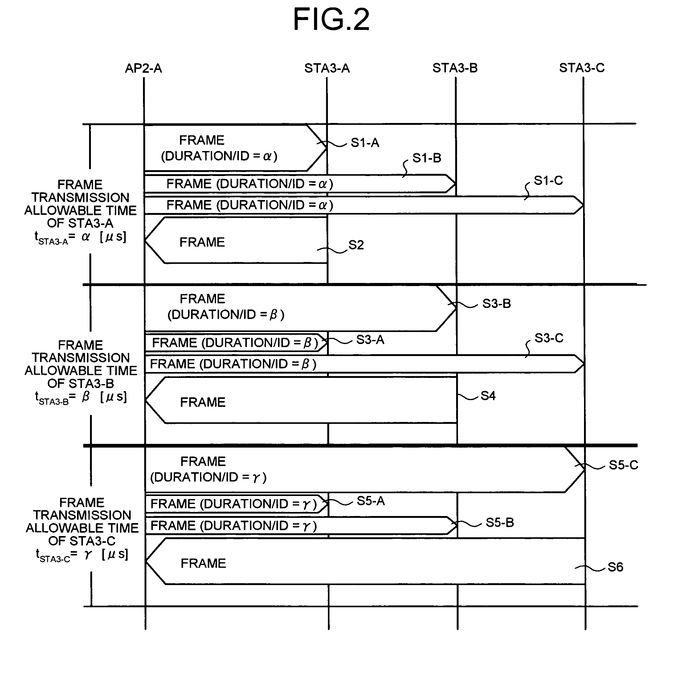
[0079] In the second embodiment, the transmission allowable time for the wireless terminal stations (STA) 3 in the first embodiment is set equal to all wireless terminal stations (STA) 3, that is, set isochronously. The transmission control frame in which the isochronous transmission allowable time is set is transmitted to all the wireless terminal stations (STA) 3.

[0080] After having received the transmission control frame transmitted from the wireless base station (AP) 2, only the wireless terminal station (STA) 3 specified as an object to which the transmission allowable time is applied in the transmission control frame can transmit a data frame to the wireless base station (AP) 2 during the transmission allowable time set in the transmission control frame. The i...

third embodiment

[0104] In a third embodiment, an example in which in the wireless communication system shown in FIG. 1, the transmission allowable time is set, taking into consideration a request from the wireless base station (STA), will be explained.

[0105] In the third embodiment, the respective wireless terminal stations (STA) 3 request desired transmission allowable time, at which allocation of the transmission allowable time to the own wireless terminal station (STA) 3 is desired at the time of transmitting the transmission control frame next time, to the wireless base station (AP) 2. In other words, each of the wireless terminal stations (STA) 3 sets the desired transmission allowable time at the time of transmitting the data frame and transmits the set desired transmission allowable time to the wireless base station (AP) 2. For example, when it is desired the wireless terminal station (STA) to transmit a data frame larger than the normal data frame during the next transmission allowable tim...


PUM


Abstract

A setting unit sets a specified time serving as a clear-to-send time, during which a two-way frame transmission is possible between a local wireless base station and a wireless terminal station accommodated in the wireless base station, and as a wireless-channel reservation time used for a frame transmission between the wireless base station and the wireless terminal station, and wireless terminal station specifying information for specifying a wireless terminal station to which the specified time is applied, in a transmission control frame. A transmitting unit transmits the transmission control frame to the wireless terminal station.

Description

TECHNICAL FIELD [0001] The present invention relates to a wireless communication system conforming to the IEEE 802.11a, b, and g, including a wireless base station and a plurality of wireless terminal stations accommodated in the wireless base station, and a wireless base station used for the wireless communication system. More specifically, the invention relates to a wireless communication system and a wireless base station, which prevent frame collisions under a condition that a Distributed Coordination Function (DCF) is adopted and control traffic between wireless terminal stations, thereby realizing excellent wireless communications. BACKGROUND ART [0002] Conventionally, as an access method specified in the IEEE 802.11 in a wireless LAN system, the Distributed Coordination Function (DCF) method as the essential function and a Point Coordination Function (PCF) method as an optional function are defined. [0003] The DCF method uses Carrier Sense Multiple Access with Collision Avoid...

Claims


Application Information

Patent Timeline
IPC IPC(8): H04Q7/20H04W74/02
CPCH04W74/0816
Inventor TOMISAWA, TOSHIAKINAGAI, HIROSHISHIROKURA, TOSHIHIKO
Owner MITSUBISHI ELECTRIC CORP
Learn More