
Multi-Wideband Communications over Power Lines

Inactive Publication Date: 2007-04-05
AVAGO TECH WIRELESS IP SINGAPORE PTE +1
View PDF100 Cites 54 Cited by
  • Summary
  • Abstract
  • Description
  • Claims
  • Application Information

AI Technical Summary

Benefits of technology

[0015] In some embodiments, the power line communication device is configured to improve the throughput / coverage / cost performance trade-off of a power line network, when compared with current-generation PLC networks, by spreading the transmission of data into a plurality of independent wide band frequency bands that can be operated simultaneously and / or independently.
[0040] In some embodiments, the network interface device can combine and partition data communicated across different paths to maximise performance, coexistence and interoperability whilst minimizing system cost.

Problems solved by technology

However, the use of such low transmission frequencies limits the maximum data throughput obtainable by PLC systems.
However, there are no analog systems available for combining two or more broadband PLC technologies that can work simultaneously.
In common with most communication systems, one of the main problems with prior art PLC systems is obtaining high throughput and wide coverage at reasonable implementation cost, whilst maintaining compatibility with existing technologies.
Although a few PLC systems that provide transmission rates of hundreds of megabits per second are currently on the market, these systems have high implementation costs as they employ high bps / Hz modulation schemes (i.e. approximately 10 bps / Hz) which require high accuracy data converters, extremely linear interface electronics and increase the cost of the digital implementation due to the computational complexity of the modulation.

Method used


Image

  • Multi-Wideband Communications over Power Lines
  • Multi-Wideband Communications over Power Lines
  • Multi-Wideband Communications over Power Lines

Examples


second embodiment

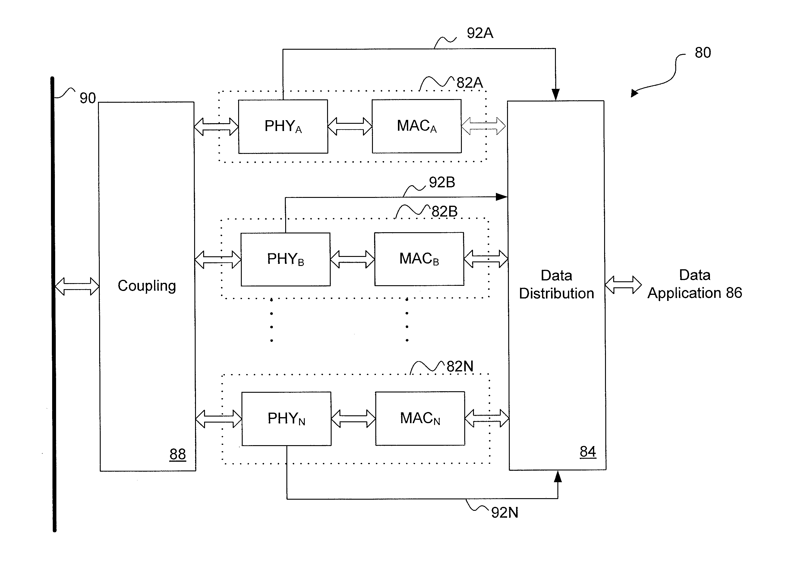
[0136] Referring to FIG. 4D in the improved network interface device there are two coupling units 166, 176, wherein coupling unit 166 is used for low band communication and coupling unit 176 is used for high band communication. In addition to the optimisation of the low band paths (167-171 and 172-175) and the high band paths (177-181 and 182-185) for the power, frequency and modulation schemes of different PLC technologies, the coupling units 166, 176 can be optimised to have different pass-frequency characteristics.

third embodiment

[0137] Referring to FIG. 4E, in the improved network interface device, there are two coupling units 186 and 190, wherein coupling unit 186 is used for reception and coupling unit 190 is used for transmission. However, each high band path (188-191 and 203-206) is isolated from the low band paths (192-195 and 197-201) by deliberately inserted filters 187, 202 with high pass or band pass characteristics.

fourth embodiment

[0138]FIG. 4F shows the improved network interface device, applied to two different wide band technologies as in FIG. 4E. Whilst there are many possible other combinations, it is not necessary for there to be separate paths and converters for the high band paths and low band paths in either the receiver or transmitter, as communications in one direction may benefit more from the improved network interface device than communications in the other direction.

[0139] The improved network interface device comprises one coupling unit for transmission 218 and one for reception 208. The high band is isolated from the low-band on the receiver path, by deliberately inserted filters 209 with high-pass or band-pass characteristics. However, the transmitter modulation schemes are combined in the digital domain 222A, 222B and then passed through a very high performance DAC (digital to analog converter) 221, smoothing filter 220 and line driver 219.

[0140] Referring to FIG. 5A, an exemplary integrat...


PUM


Abstract

Systems and methods for communicating over a power line are configured to substantially simultaneously communicate over a plurality of wide band frequency ranges. Signals may be communicated two or from a communication node at two different frequencies simultaneously. These signals may be exchanged with different nodes and / or include independent data. In some embodiments, some of the wide band frequency ranges are above 30 MHz.

Description

CROSS-REFERENCE TO RELATED APPLICATIONS [0001] This Application is a continuation-in-part of U.S. patent application Ser. No. 11 / 467,141 filed Aug. 24, 2006 and entitled “Multi-Wide band Communications over Power Lines”; this application further claims benefit of and priority to European Patent Application EP 05 256 179.2, entitled “Power line Communication Device and Method,” filed Oct. 4, 2005 under 35 U.S.C. 119. The disclosure of the above patent application is hereby incorporated herein by reference.BACKGROUND [0002] 1. Field of the Invention [0003] The present invention relates to systems and methods for power line communication and in particular, systems and methods for wide band power line communication. [0004] 2. Related Art [0005] With the growing use of digital content (e.g. MP3 audio, MPEG4 video and digital photographs) there is a widely recognised need to improve digital communication systems. Power line communication (PLC) is a technology that encodes data in a signal...

Claims


Application Information

Patent Timeline
IPC IPC(8): H04B7/216
CPCH04B3/54H04B2203/5408H04B2203/5416H04B2203/5445H04B2203/545H04B2203/5454
Inventor RIVEIRO, JUAN CARLOSFOUREN, NILS HAKANHURWITZ, JONATHAN EPHRAIM DAVID
Owner AVAGO TECH WIRELESS IP SINGAPORE PTE
Learn More