Supercharge Your Innovation With Domain-Expert AI Agents!

EGR control system for internal combustion engine

a control system and internal combustion engine technology, applied in the direction of electrical control, process and machine control, etc., can solve the problems of fuel economy, drivability, exhaust emission, and control accuracy degraded, so as to improve the control accuracy of in-cylinder temperature and high accuracy

Inactive Publication Date: 2007-04-05
HONDA MOTOR CO LTD
View PDF9 Cites 39 Cited by
  • Summary
  • Abstract
  • Description
  • Claims
  • Application Information

AI Technical Summary

Benefits of technology

The present invention provides an EGR control system for an internal combustion engine that can accurately control the amount of recirculated gas in the cylinder, with high accuracy, to improve control accuracy of in-cylinder temperature. The system includes a low-temperature gas recirculation device and a high-temperature gas recirculation device, which can change the recirculation amount of low-temperature gas and high-temperature gas in response to operating conditions of the engine. The system also includes an EGR rate parameter-calculating means for accurately calculating the EGR rate parameter, a target value-setting means for setting the target value of the EGR rate parameter, a feedback correction value-calculating means for calculating the feedback correction value, and a control means for controlling one or both of the low-temperature gas recirculation device and the high-temperature gas recirculation device. The system can improve fuel economy, drivability, and exhaust emission control, and can be applied to both internal combustion engines and hybrid vehicles.

Problems solved by technology

Therefore, control accuracy in EGR control is relatively low, which degrades accuracy in control of in-cylinder temperature as well.
For these reasons, there is a fear that fuel economy, drivability, and exhaust emission might be all degraded.
Further, the conventional EGR control system cannot be applied to an engine, such as a compression ignition combustion engine, which requires highly accurate control of in-cylinder temperature in combustion of a mixture.
Therefore, in changing the internal EGR amount, it is required to relatively largely change the intake and exhaust cam phases, and it takes time before the intake and exhaust cam phases are actually changed in response to associated control signals after delivery of the signals to the variable valve actuating mechanisms, i.e. the variable valve actuating mechanisms suffer from response delay, so that the control of the internal EGR amount is low in responsiveness, which makes it impossible to promptly control the internal EGR amount to a desired EGR amount.
Further, to control the internal EGR amount, it is necessary to calculate the overlap area between respective non-linear valve lift curves of the intake and exhaust valves, and for accurate calculation of the overlap area, it is required to execute complicated computing operations, such as integral operations, which increases computation load.
Therefore, when the EGR rate is low, the actual EGR rate cannot be detected with accuracy, so that the actual EGR rate cannot be accurately controlled to the target EGR rate.
Further, it is required to provide the oxygen concentration sensor in the intake pipe only for determining the actual EGR rate, which is disadvantageous in costs.
However, in performing what is called internal EGR in which part of combustion gases are caused to remain in the combustion chamber without being exhausted therefrom, it is impossible to accurately calculate an internal EGR rate which is a ratio of an amount of combustion gases to a total amount of gases existing in the combustion chamber.

Method used


Image

  • EGR control system for internal combustion engine
  • EGR control system for internal combustion engine
  • EGR control system for internal combustion engine

Examples


Embodiment Construction

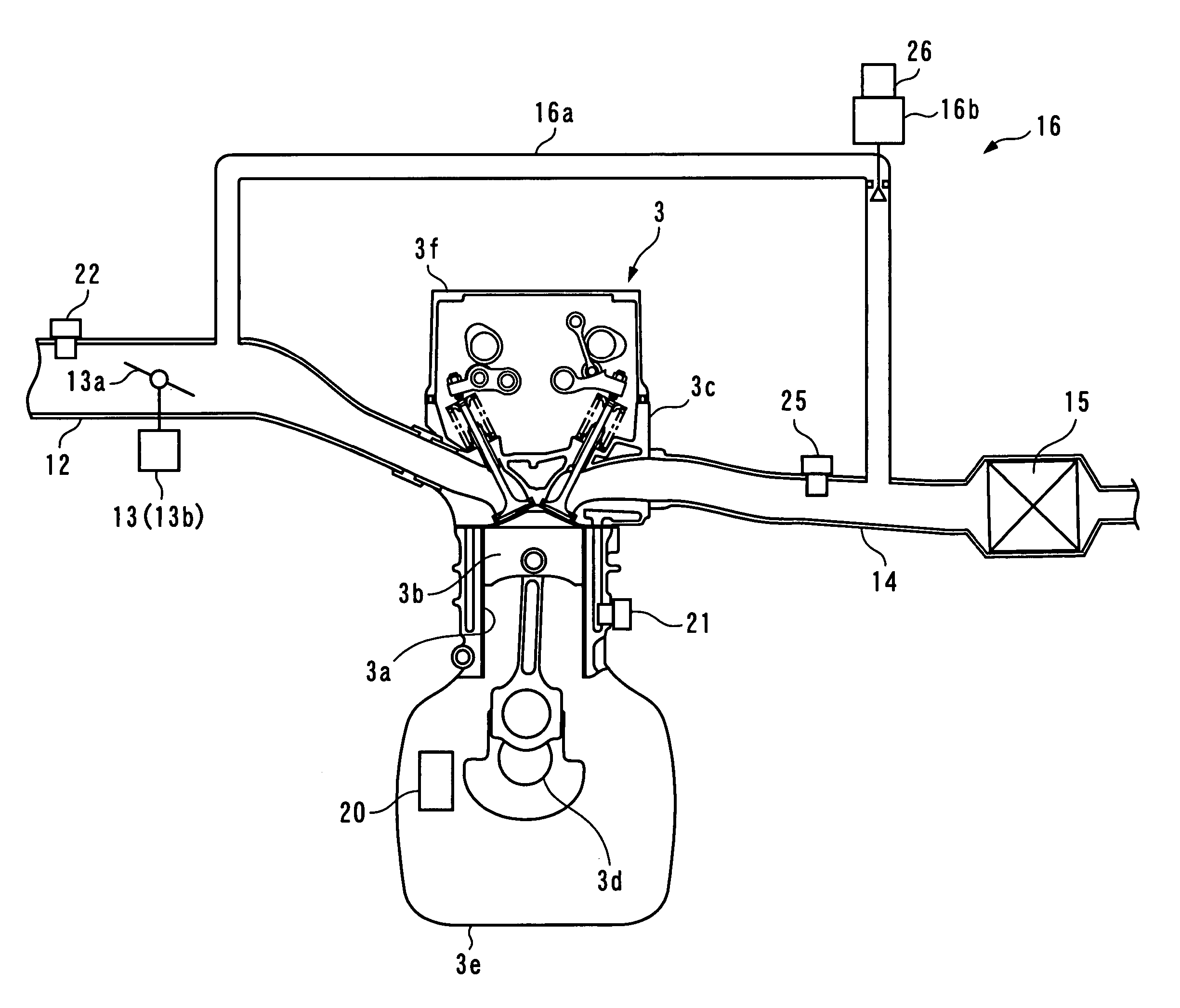
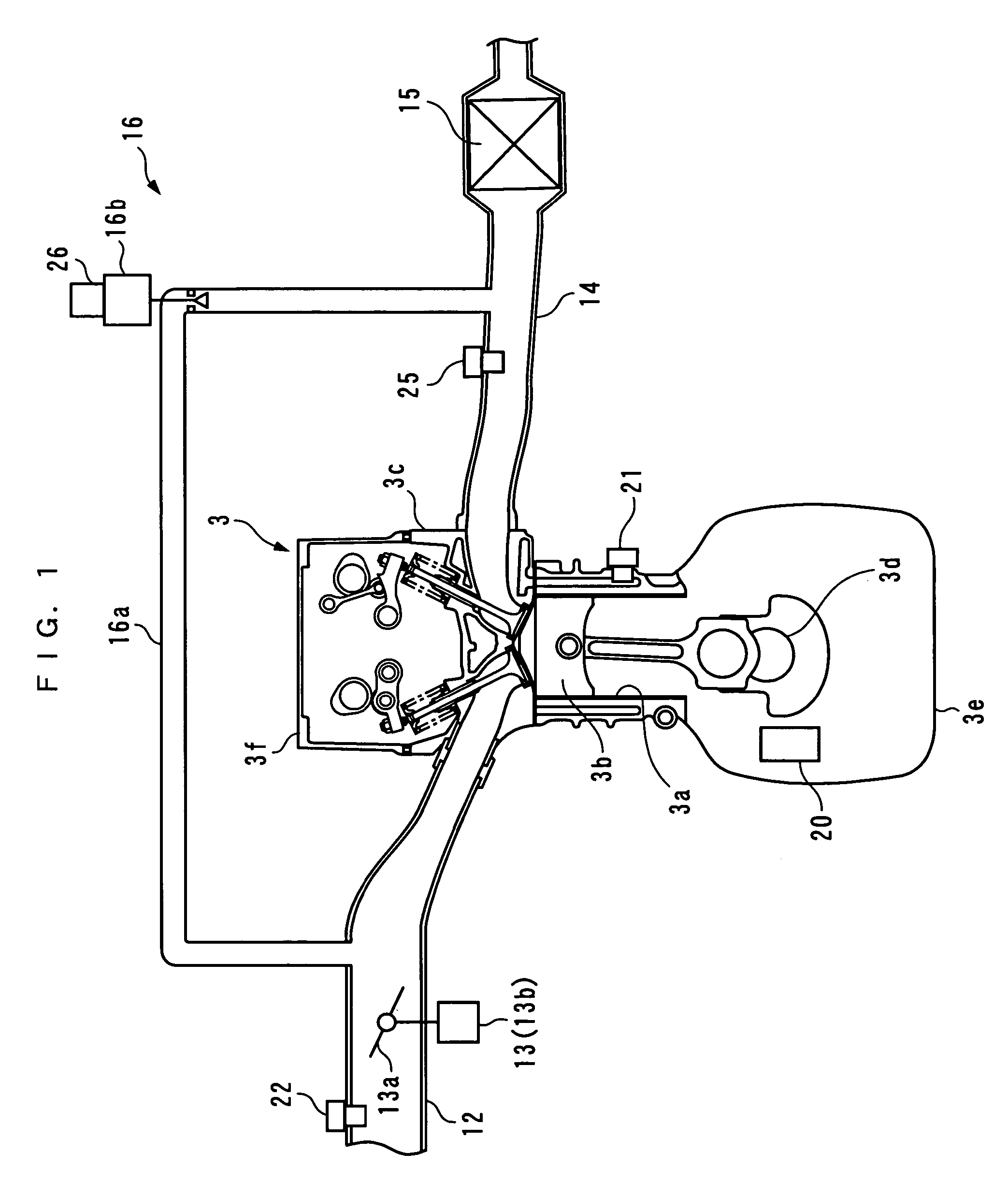
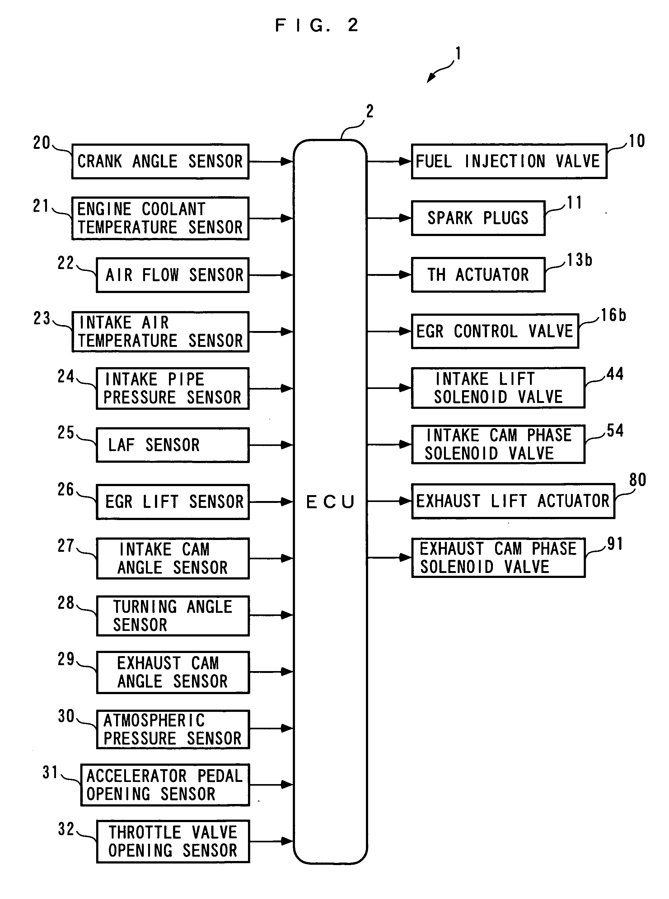
[0074] The present invention will now be described in detail with reference to the drawings showing a preferred embodiment thereof. FIG. 2 is a block diagram showing an EGR control system for an internal combustion engine (hereinafter referred to as “the engine”) 3, according to the embodiment of the present invention. As shown in FIG. 2, the EGR control system 1 includes an ECU 2. The ECU 2 carries out control processes, as described hereinafter, including an EGR control process, depending on operating conditions of the engine 3.

[0075] As shown in FIGS. 1 and 3, the engine 3 is an inline four-cylinder gasoline engine installed on an automotive vehicle, not shown, and has four pairs (only one of which is shown) of cylinders 3a and respective pistons 3b associated therewith. Further, the engine 3 has a combustion chamber 3g defined between the piston 3b in each cylinder 3a and a cylinder head 3c.

[0076] The engine 3 includes, on a cylinder-by-cylinder basis, a pair of intake valves ...


PUM


Abstract

An EGR control system that is capable of controlling the amount of recirculation of high-temperature and low-temperature recirculated gases, with high accuracy, to thereby improve the control accuracy of in-cylinder temperature. An ECU of an ERG control system calculates a fresh intake air ratio, and sets a target value of the fresh intake air ratio. The ECU calculates a feedback correction coefficient for converging the fresh intake air ratio to the target value, with an I-PD control algorithm, and sets an external EGR ratio and an internal EGR ratio. The ECU controls the EGR amount whose ratio is the larger, according to the larger one of the two ratios and the feedback correction coefficient, and controls the EGR amount whose ratio is the smaller, according to the smaller of the ratios and the learned value thereof.

Description

BACKGROUND OF THE INVENTION [0001] 1. Field of the Invention [0002] The present invention relates to an EGR control system for an internal combustion engine, for controlling high-temperature and low-temperature recirculated gases, particularly to an EGR control system for an internal combustion engine, for controlling internal EGR in which combustion gases generated by combustion are caused to remain in a cylinder, and more particularly to an EGR control system for an internal combustion engine, for controlling the internal EGR by changing lift of exhaust valves by an exhaust valve lift mechanism. [0003] 2. Description of the Related Art [0004] Conventionally, an EGR control system for an internal combustion engine, of the above-mentioned kind, has been disclosed e.g. in the publication of Japanese Patent Publication No. 3305416 (first prior art). This engine is of a spark ignition type, and includes a low-temperature EGR device and a high-temperature EGR device. The low-temperature...

Claims


Application Information

Patent Timeline
Patent Type & Authority Applications(United States)
IPC IPC(8): F02M25/07F02B47/08F01L1/34
CPCF02D13/0219F02D13/0246F02D13/0265F02D41/006F02D41/0062F02D41/0065F02D41/0072F02D41/187F02D2041/001F02D2041/1409F02D2200/0406F02M25/0752F02M25/0756Y02T10/47Y02T10/18F02M26/01F02M26/48Y02T10/12Y02T10/40
Inventor OGAWA, KENKITAMURA, TORUUMEMOTO, ATSUSHISHINOHARA, TOSHINARISUGIMOTO, MITSURUNAKANO, TETSUAKI
Owner HONDA MOTOR CO LTD
Features
  • R&D
  • Intellectual Property
  • Life Sciences
  • Materials
  • Tech Scout
  • Unparalleled Data Quality
  • Higher Quality Content
  • 60% Fewer Hallucinations
Learn More