Method and device for bidirectional single-wire data transmission

a data transmission and bidirectional technology, applied in the field of bidirectional single-wire data transmission, can solve the problems of uploading information, bus systems are not suitable for real-time systems,

Active Publication Date: 2007-03-29
ROBERT BOSCH GMBH
View PDF3 Cites 18 Cited by
  • Summary
  • Abstract
  • Description
  • Claims
  • Application Information

AI Technical Summary

Benefits of technology

[0006] The method according to the present invention and the corresponding device have the advantage in relation to the known approaches that a fail-safe interface having only one line between the control unit and the particular peripheral unit to be activated, such as an ignition coil or a fuel injector of a motor vehicle engine, is provided, the interface having real-time capability for the existing chronological conditions, as they exist in ignition systems or injection systems in motor vehicles, for example.

Problems solved by technology

These bus systems are not suitable for real-time systems, however, i.e., for immediate triggering of the switching operation in the microsecond range, but rather solely for non-time-critical data exchange in the millisecond range of spatially distributed systems.
Further systems have the disadvantage that they may only upload information during activation of the peripheral unit by the control unit.

Method used


Image

  • Method and device for bidirectional single-wire data transmission
  • Method and device for bidirectional single-wire data transmission
  • Method and device for bidirectional single-wire data transmission

Examples


Embodiment Construction

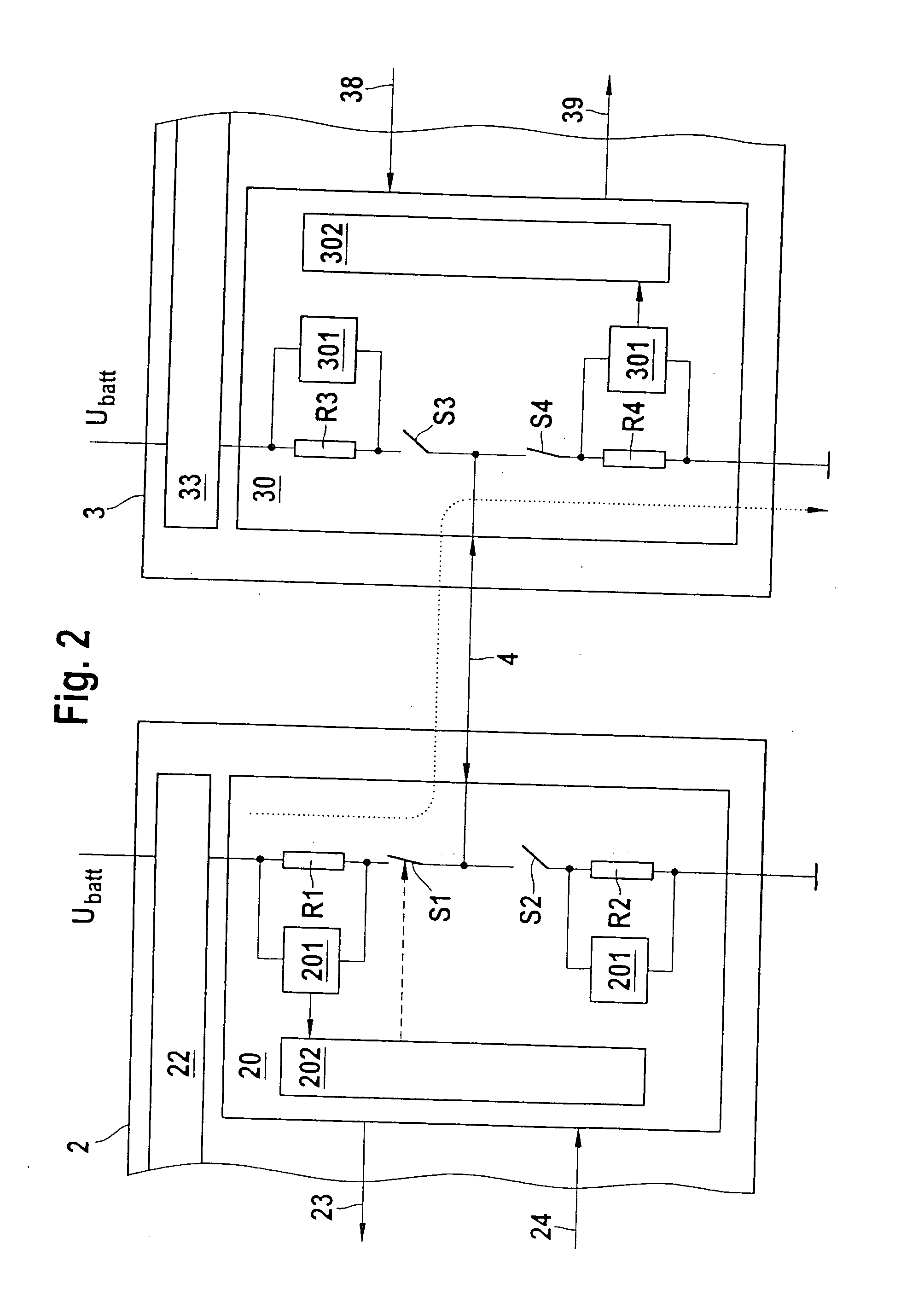
[0035] Identical reference numerals identify identical or functionally identical components in the figures.

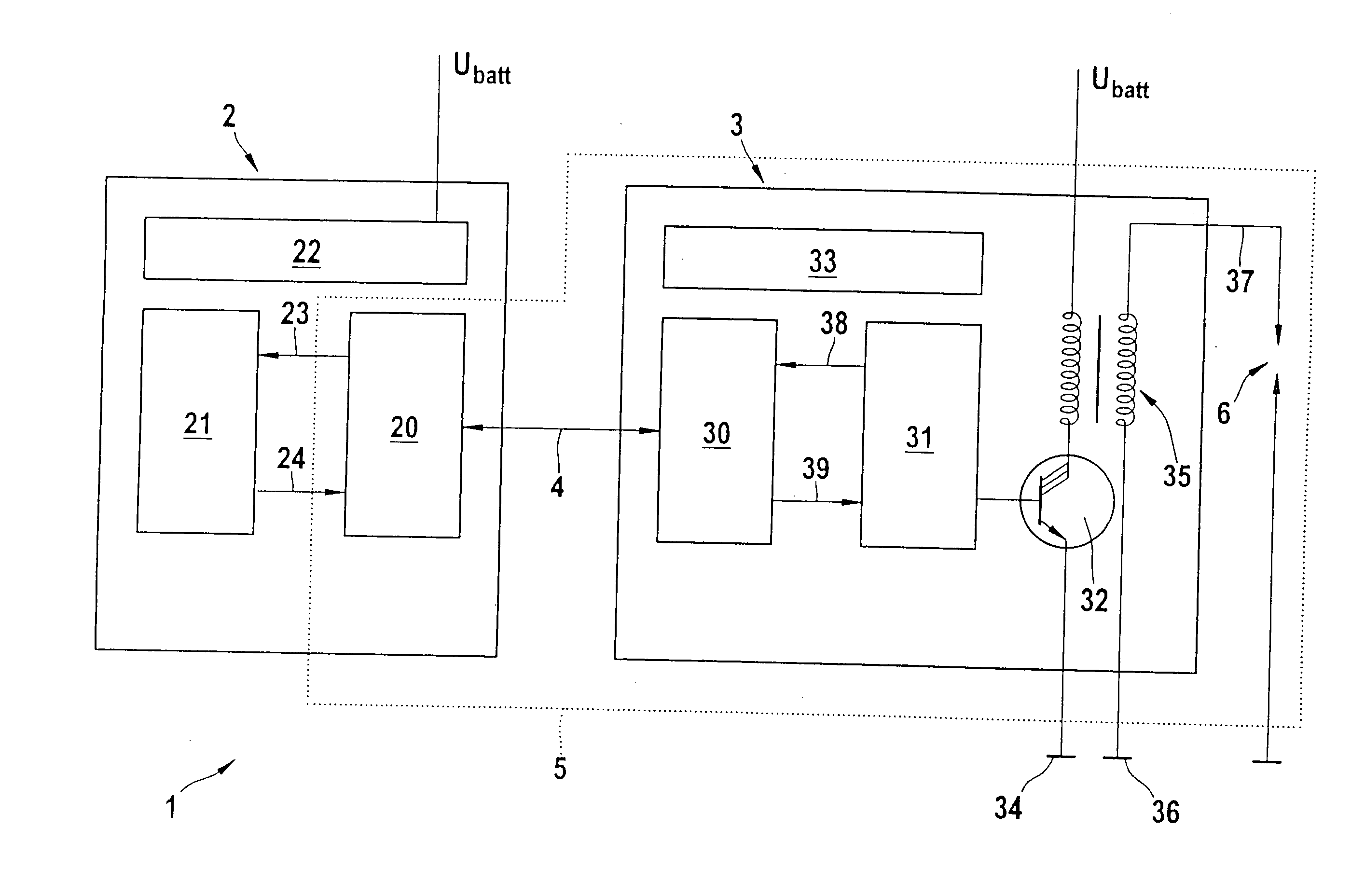
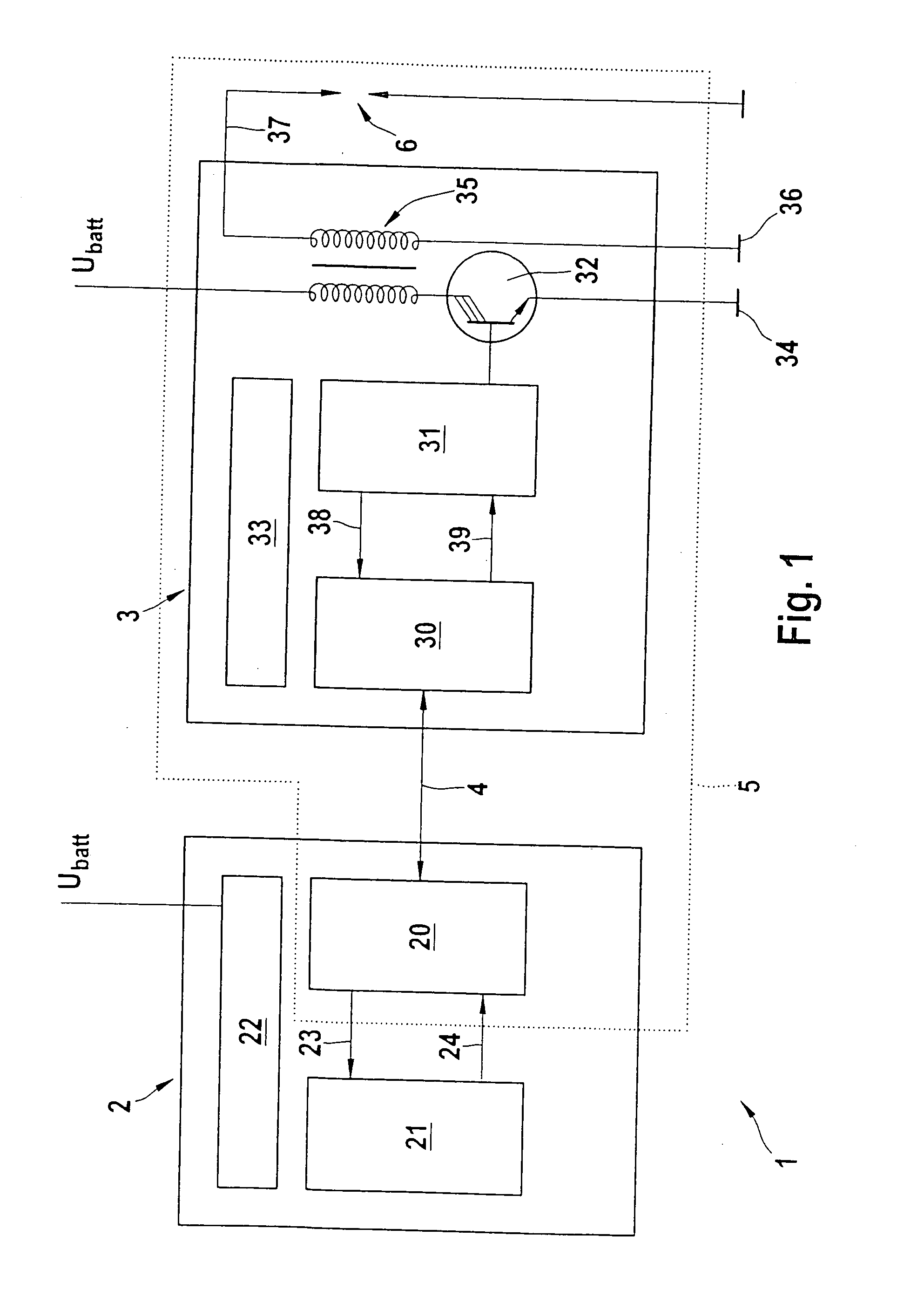
[0036]FIG. 1 shows a schematic illustration of a device 1 for bidirectional transmission of data information via a single-wire line 4 between a control unit 2 and a peripheral unit 3 having an ignition coil 35, a fuel injector of a motor vehicle engine, a sensor or an actuator, or the like, for example.

[0037] In the following, the device is to be explained with reference to FIG. 1 as an example in regard to an ignition system 5 of a motor vehicle engine. Ignition system 5 includes, for example, a spark plug 6, a high-voltage connection 37, an ignition coil 35, an ignition trigger, such as a logic 31, an ignition output stage 32, a voltage supply 33, and a driver circuit 30 in a peripheral unit 3 and an engine control unit 2 having an ignition driver 20. Control unit 2 additionally contains an electronic controller 21 and a power supply 22.

[0038] Controller 21 is connected to...


PUM


Abstract

A device and a method are described for bidirectional single-wire data transmission of information between a control unit and at least one peripheral unit, having the following steps: generating a first current flow from the control unit to the peripheral unit during first time slots via a single-wire line to transmit voltage-coded or current-coded information from the control unit to the peripheral unit; and/or generating a second current flow from the peripheral unit to the control unit during second time slots via the single-wire line to upload voltage-coded or current-coded information from the peripheral unit to the control unit; the first and second time slots being implemented so they do not mutually overlap; and/or generating, in the first and/or second time slots, additional information to be transmitted and/or uploaded, which is transmitted as digital or analog signals by modulating the current or the voltage of the single-wire line and is analyzed in the control unit or the peripheral unit.

Description

FIELD OF THE INVENTION [0001] The present invention relates to a method and a device for bidirectional single-wire data transmission of data information between a control unit and at least one peripheral unit, the function of the single-wire line being able to be diagnosed. BACKGROUND INFORMATION [0002] Although it is applicable to any arbitrary systems which include a control unit and at least one peripheral unit connected thereto using a line, the present invention and the set of problems on which it is based will be explained in relation to an ignition system or an injection system for gasoline engines in the field of motor vehicles, for example. [0003] In current motor vehicle technology, systems are used in which peripheral units are connected via lines to a control unit. In this case, the corresponding peripheral units are usually spatially separated from the control unit, because of which special requirements are to be placed on the lines and the interfaces. [0004] Some inter...

Claims


Application Information

Patent Timeline
Patent Type & Authority Applications(United States)
IPC IPC(8): G05D1/00G06F17/00H04L5/16H04L12/417
CPCF02P3/083H04L2012/40215H04L12/417H04L5/16
Inventor KRAEMER, ROLFBENTEL, ULRICHEISELE, BERNHARDKETTERER, MARKUSSCHILLER, UWESTEIN, JUERGEN
Owner ROBERT BOSCH GMBH
Why Eureka
Try Eureka