
Process apparatus with on-the-fly workpiece centering

Active Publication Date: 2007-03-29
BOOKS AUTOMATION US LLC
View PDF14 Cites 68 Cited by
  • Summary
  • Abstract
  • Description
  • Claims
  • Application Information

AI Technical Summary

Benefits of technology

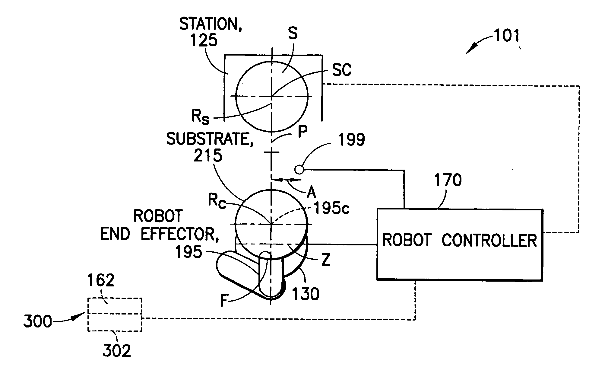
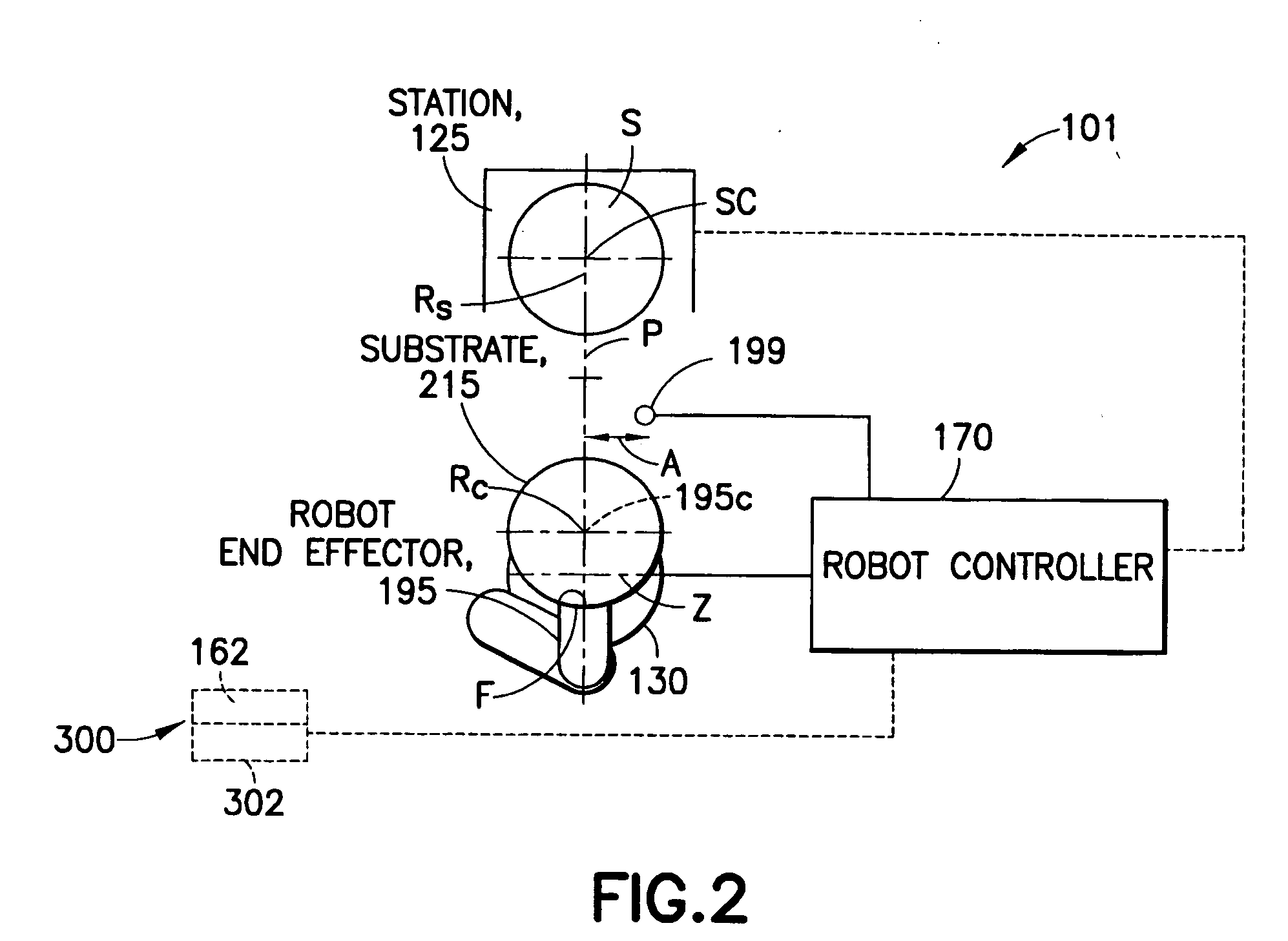
[0011] In accordance with one exemplary embodiment a substrate processing apparatus is provided. The processing apparatus has a transport apparatus, at least one sensor connected to the transport apparatus and a controller. The transport apparatus is adapted for transporting the substrate between processing stations of the processing apparatus. The sensor is capable of sensing the substrate transported by the transporting apparatus. The sensor is arranged f

Problems solved by technology

As a result of limited, but not negligible, motion of the substrates in the cassettes during transportation, the robot may pick the substrate with undesirable eccentricity or misalignment.
Though this approach may be satisfactory initially, subsequent pics and placements of the substrate, such as may occur with multi step process tools where substrates may be transported serially between multiple process steps, may result in the location of the substrate shifting relative to its desired location in the various stations.
This approach introduces undesirable delays associated with the additional pick-place operations and with the additional and redundant edge-scanning process, all of which are executed sequentially rather than in an on-the-fly manner.
However, the mass and complexity of the moving components of the robot arm increases undesirably, which results in limited speed, compromised reliability and a higher cost.
However, one disadvantage of this method is that it requires an array of multiple sensors.
The wafer position calculated by the disclosed conventional system is affected by dimensional variations of the wafers, and the conventional system is not capable of compensating for wafer variances when determining the position adjustment to correct wafer position eccentricity.

Method used


Image

  • Process apparatus with on-the-fly workpiece centering
  • Process apparatus with on-the-fly workpiece centering
  • Process apparatus with on-the-fly workpiece centering

Examples


Embodiment Construction

[0003] The exemplary embodiments disclosed herein relate to a substrate processing apparatus and, more particularly, to a substrate processing apparatus with on-the-fly substrate centering.

[0004] 2. Brief Description of Related Developments

[0005] Typical manufacturing processes for semiconductor integrated circuits may utilize robotic manipulators to cycle substrates, for example, circular silicon wafers, through pre-determined sequences of operations in fully automated processing equipment. Substrates may be delivered to the substrate processing equipment, also referred to as a tool, in standard transportation cassettes which house a batch of substrates stored in horizontal slots. Individual substrates may then be transferred from the cassettes by a specialized pick-place robot which may be integrated into the tool. Typically, the robot holds a substrate by means of frictional force between the backside of the substrate and an end-effector. In some applications, the force may be ...


PUM


Abstract

A substrate processing apparatus having a transport apparatus, at least one sensor connected to the transport apparatus and a controller. The transport apparatus is adapted for transporting the substrate between processing stations of the processing apparatus. The sensor is capable of sensing the substrate transported by the transporting apparatus. The sensor is arranged for sending at least one signal in response to sensing the substrate. The controller is communicably connected to the sensor and arranged to determine alignment of the substrate in at least two directions, angled relative to each other, relative to a predetermined location. The controller is capable of determining alignment from the at least one signal identifying no more than two points on the substrate and independent of radial variances between substrates.

Description

CROSS-REFERENCE TO RELATED APPLICATION(S) [0001] This application claims the benefit of U.S. Provisional Application No. 60 / 698,536, filed Jul. 11, 2005, which is incorporated by reference herein in its entirety.BACKGROUND [0002] 1. Field of the Exemplary Embodiments [0003] The exemplary embodiments disclosed herein relate to a substrate processing apparatus and, more particularly, to a substrate processing apparatus with on-the-fly substrate centering. [0004] 2. Brief Description of Related Developments [0005] Typical manufacturing processes for semiconductor integrated circuits may utilize robotic manipulators to cycle substrates, for example, circular silicon wafers, through pre-determined sequences of operations in fully automated processing equipment. Substrates may be delivered to the substrate processing equipment, also referred to as a tool, in standard transportation cassettes which house a batch of substrates stored in horizontal slots. Individual substrates may then be tr...

Claims


Application Information

Patent Timeline
IPC IPC(8): H01L21/677
CPCH01L21/67265
Inventor GILCHRIST, ULYSSESOLIVERA, HANIELFOSNIGHT, WILLIAMPICKREIGN, RICHARDCAVENEY, ROBERT
Owner BOOKS AUTOMATION US LLC
Learn More