Radial out-flowing rotary ram-in compressor

a compressor and ram-in technology, applied in the direction of machines/engines, stators, liquid fuel engines, etc., can solve the problems of the practical useful range of operating rotational speeds and the inconvenience of use of the conventional type of positive displacement rotary compressors

Inactive Publication Date: 2007-03-22
RRC SGTE TECH
View PDF5 Cites 0 Cited by
  • Summary
  • Abstract
  • Description
  • Claims
  • Application Information

AI Technical Summary

Benefits of technology

[0006] The present invention provides a rotary positive displacement compressor having no rubbing parts within, which allows its use in the applications wherein relatively high operating rotational speeds are needed.
[0012] In another preferred embodiment, in order to increase the volumetric rate with which the working gases are fed to the radial out-flowing rotary ram-in compressor of the present invention, each of the feeding channels is slightly converging from its inlet towards its outlet. The convergence of the feeding channel is provided by designing the boundaries confining the channel between them so that the axial width of the channel and / or the width between the opposing parts of the surfaces of the two adjacent vanes confining the channel between them decrease preferably gradually from the inlet of the channel towards its outlet, and hence, the cross-sectional area of the channel decreases preferably gradually from its inlet towards its outlet.
[0016] In another preferred embodiment, a successive rotary ram-in compressor (either a radial in-flowing or a radial out-flowing one) is used for active sweeping of gases from the compressor's receiver, as the static pressure rise developed within the receiver of the second rotary ram-in compressor prevents excess flow of gases from the receiver of the first radial out-flowing rotary ram-in compressor through the feeding channels of the second rotary ram-in compressor, with the density and the pressure level of the gases within the receiver of the first radial out-flowing rotary ram-in compressor being dependant on the ratio between the volumetric rate with which gases are fed to the receiver and the volumetric rate with which gases are swept from it.
[0019] The velocity of the feeding channels of the radial out-flowing rotary ram-in compressor is kept below the speed of sound to avoid the formation of shock waves, which if formed will interfere with the free ingestion of working gases by the feeding channels.

Problems solved by technology

On the contrary, conventional types of positive displacement rotary compressors are not convenient for use in gas turbine engines, and the like, as the friction between the rubbing parts within them limits their practically useful range of operating rotational speeds.

Method used


Image

  • Radial out-flowing rotary ram-in compressor
  • Radial out-flowing rotary ram-in compressor
  • Radial out-flowing rotary ram-in compressor

Examples


Embodiment Construction

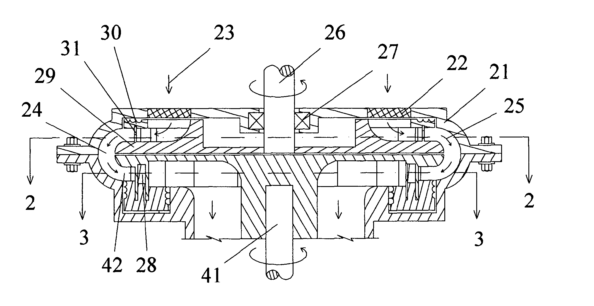
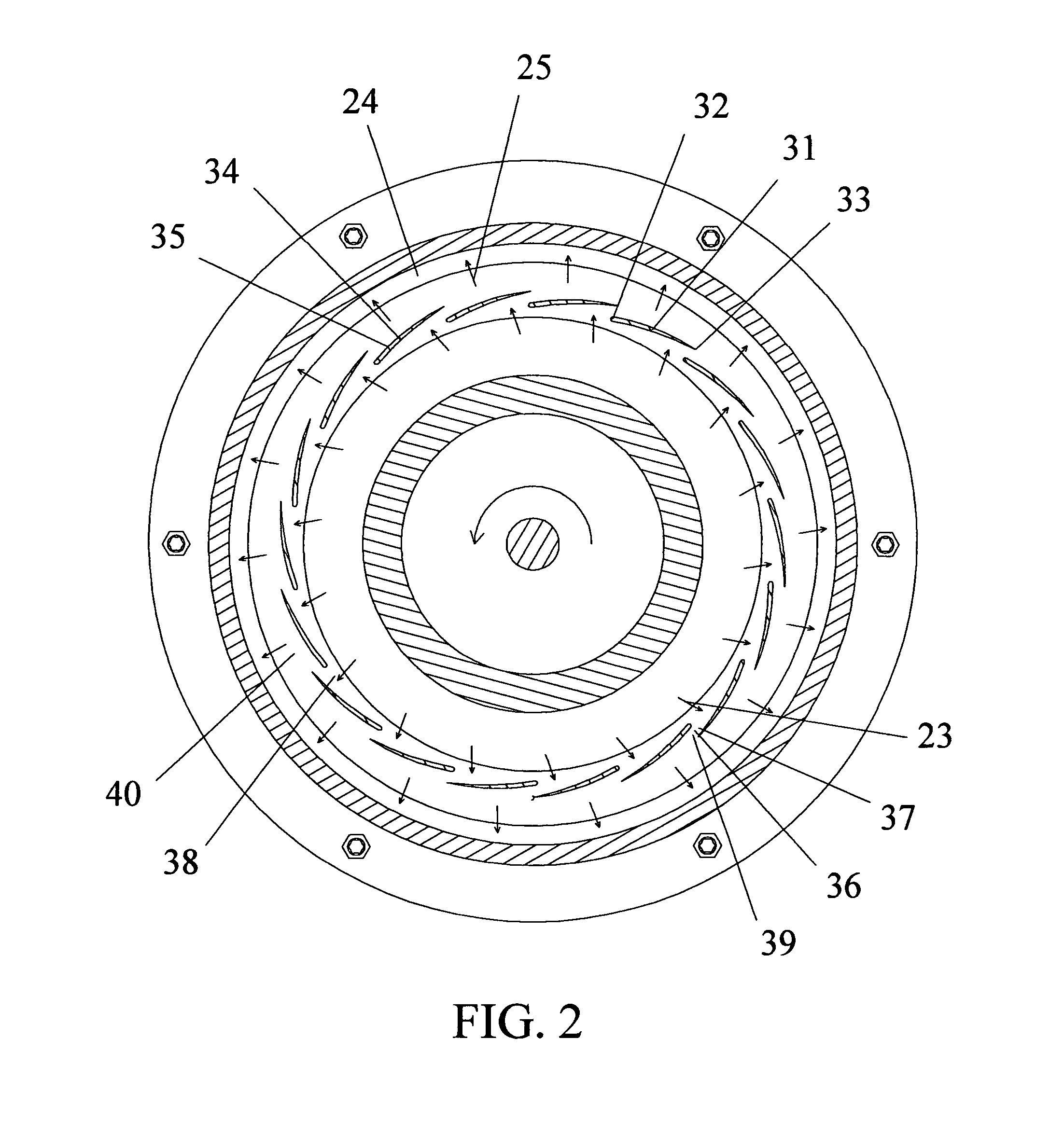
[0026] Prior filed U.S. patent application Ser. No.10 / 669,514, entitled “Rotary ram-in compressor” provides a rotary ram-in compressor for use in gas turbine engines, and the like, having a plurality of vanes attached to discs, with the opposing parts of each two adjacent vanes defining a feeding channel in-between. In operation, working gases are rammed through the feeding channels, followed by positive displacement of the rammed-in gases to a receiver wherein pressurized gases collect. The pressurized gases are actively swept from the receiver by either a successive rotary ram-in compressor or a successive rotary ram compressor (disclosed in the inventor's earlier International Patent Application Number: PCT / US00 / 17044, entitled “Rotary ram fluid pressurizing machine”). In the exemplary embodiments provided in the before mentioned prior patent application, working gases are displaced in a generally radially inward direction, which makes it inconvenient for use in the applications ...


PUM


Abstract

A radial out-flowing rotary ram-in compressor for use in gas turbine engines and the like, having a plurality of vanes attached to discs, with the opposing parts of each two adjacent vanes defining a feeding channel in-between. In operation, working gases are rammed through the feeding channels in a generally radially outward direction, followed by positive displacement of the rammed-in gases to a receiver wherein pressurized gases collect. The pressurized gases are actively swept from the receiver by either a successive rotary ram-in compressor or a successive rotary ram compressor.

Description

CROSS-REFERENCE TO RELATED APPLICATION(S) [0001] This non-provisional utility patent application claims the benefit of one prior filed co-pending non-provisional application; the present application is a continuation-in-part of U.S. patent application Ser. No. 10 / 669,514, filed Sep. 23, 2003, which is incorporated herein by reference in its entirety.FIELD OF THE INVENTION [0002] The present invention relates to a positive displacement compressor and, more particularly, to a rotary positive displacement compressor convenient for use in gas turbine engines and the like. BACKGROUND OF THE INVENTION [0003] Rotary compressors are well known devices, used in several fields to develop a pressure gradient between two points across a stream of working gases. Two main types of rotary compressors are in use, dynamic compressors, i. e., centrifugal flowing, axial flowing, and the combined types, and positive displacement compressors. In dynamic compressors the working gases are accelerated foll...

Claims


Application Information

Patent Timeline
Patent Type & Authority Applications(United States)
IPC IPC(8): F04D29/44F04D29/54
CPCF04D29/54F04D29/44F01D1/06
Inventor AWDALLA, ESSAM T.
Owner RRC SGTE TECH
Why Eureka
Try Eureka