
Method and circuitry to generate a reference current for reading a memory cell, and device implementing same

a reference current and memory cell technology, applied in static storage, digital storage, instruments, etc., can solve the problems of reducing the margin of operation, unavoidable variations of commercial devices, and reducing the variance of electrical characteristics corresponding to the different digital states

Active Publication Date: 2007-03-22
MICRON TECH INC
View PDF99 Cites 149 Cited by
  • Summary
  • Abstract
  • Description
  • Claims
  • Application Information

AI Technical Summary

Benefits of technology

[0032] Notably, the present inventions may be implemented in conjunction with any memory cell technology, whether now known or later developed. For example, the memory cells may include one or more electrically floating body transistors, one transistor-one capacitor architecture

Problems solved by technology

However, unavoidable variations typically exist in commercial devices because of mismatch in memory cell characteristics as well as mismatch in the transistors that comprise the circuitry (for example, the sense amplifier circuitry) which is responsible for sensing, sampling, detecting and / or discriminating between the data states.
This tends to reduce the margin of operation (for example, the read window margin).
As a result, the variance of the various electrical characteristics corresponding to the different digital states may not be constant.
Prior art midpoint reference positioning may also exhibit the drawback of having unequal read margins toward state “0” and state “1”, this latter case demonstrates a lower margin.
This lower margin may eventually translate into more failures during the read operations (and / or an overall reduction in the read window margin).

Method used


Image

  • Method and circuitry to generate a reference current for reading a memory cell, and device implementing same
  • Method and circuitry to generate a reference current for reading a memory cell, and device implementing same
  • Method and circuitry to generate a reference current for reading a memory cell, and device implementing same

Examples


Embodiment Construction

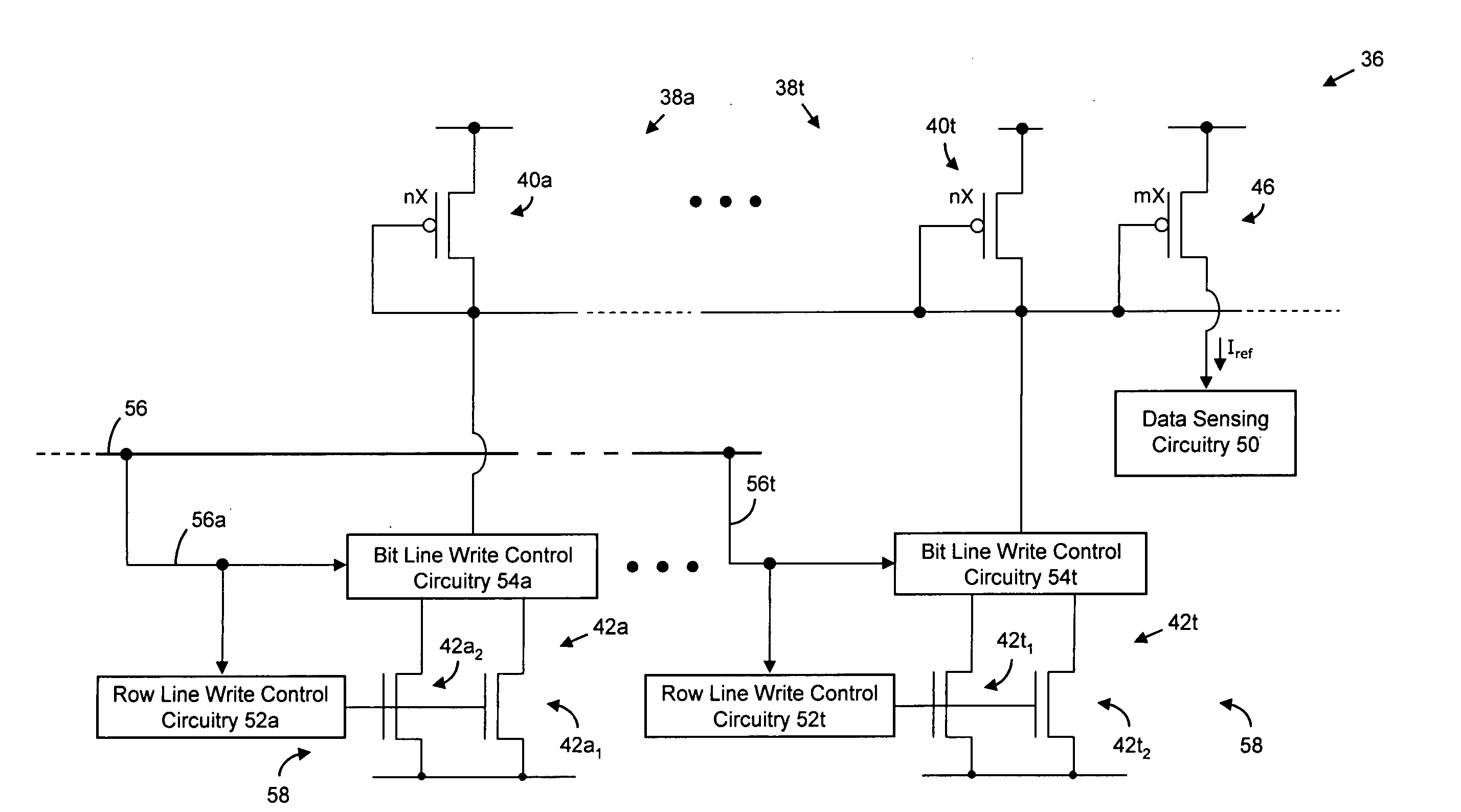
[0053] There are many inventions described and illustrated herein. In one aspect the present inventions are directed to techniques for reading, controlling and / or operating a memory cell, array, architecture and / or integrated circuit device wherein the memory cell(s) include electrically floating body transistors in which an electrical charge is stored in the body of the transistor. The present inventions are also directed to memory cell, array, architecture and device that implement circuitry to implement such reading, controlling and / or operating techniques. Notably, the memory cell and / or memory cell array may comprise a portion of an integrated circuit device, for example, logic device (such as, a microcontroller or microprocessor) or a portion of a memory device (such as, a discrete memory).

[0054] In one aspect, the present inventions control, adjust, determine and / or modify the absolute and / or relative positioning or location (i.e., the absolute or relative amount) of the ref...


PUM


Abstract

There are many inventions disclosed herein. In one aspect, the present inventions are directed to methods and circuitry to control, adjust, determine and / or modify the absolute and / or relative positioning or location (i.e., absolute or relative amount) of reference current which is employed by sensing circuitry to sense the data state of a memory cell during a read operation of one or more memory cells. The control, adjustment, determination and / or modification of the reference current levels may be implemented using many different, distinct and / or diverse techniques and circuitry, including both analog and digital techniques and circuitry.

Description

RELATED APPLICATION [0001] This application claims priority to U.S. Provisional Application Ser. No. 60 / 718,417, entitled “Method and Circuitry to Generate a Reference Current for Reading a Memory Cell Having an Electrically Floating Body Transistor, and Device Implementing Same”, filed Sep. 19, 2005. The contents of this provisional application are incorporated by reference herein in their entirety.BACKGROUND [0002] The inventions relate to a semiconductor memory cell, array, architecture and device, and techniques for controlling and / or operating such cell, array and device; and more particularly, in one aspect, to a dynamic random access memory (“DRAM”) cell, array, architecture and device, wherein the memory cell includes an electrically floating body wherein an electrical charge is stored therein. [0003] There is a continuing trend to employ and / or fabricate advanced integrated circuits using techniques, materials and devices that improve performance, reduce leakage current and...

Claims


Application Information

Patent Timeline
IPC IPC(8): G11C16/06
CPCG11C11/4099G11C7/14
Inventor BAUSER, PHILIPPE
Owner MICRON TECH INC
Learn More