
Optimally Clocked Trim Retarders

a technology of clocked trim retarders and lcd-based projection systems, applied in the direction of liquid crystal compositions, color television details, instruments, etc., can solve problems such as not providing a solution to contrast inequality

Active Publication Date: 2007-03-22
VIAVI SOLUTIONS INC
View PDF40 Cites 69 Cited by
  • Summary
  • Abstract
  • Description
  • Claims
  • Application Information

AI Technical Summary

Benefits of technology

The patent text describes a new method for improving the contrast levels of a liquid crystal display based projection system by compensating for the asymmetry in the system caused by the orientation of the liquid crystal display panel and the polarizers. The method involves using a trim retarder with an in-plane retardance greater than the residual in-plane retardance of the liquid crystal display panel and an optimal azimuthal angle range that provides a system contrast level that is substantially unaffected by the orientation of the slow axis of the liquid crystal display panel and the orientation of the polarizers. This method ensures that the same system contrast levels are achieved regardless of the orientation of the slow axis of the liquid crystal display panel and the orientation of the polarizers.

Problems solved by technology

Moreover, while the results indicate that the LCoS pretilt direction has a large impact on system contrast (i.e., the system contrast is different for different orientations of the LCoS panel for a given PBS coating surface inclination and / or for different PBS coating surface inclinations for a given LCoS orientation), they do not provide a solution to the contrast inequality.
Unfortunately, this means that LCoS engines having different panel orientations and / or different PBS orientations will exhibit different system contrasts.
This is a serious concern for manufacturers which require all products to have a same contrast ratio.

Method used


Image

  • Optimally Clocked Trim Retarders
  • Optimally Clocked Trim Retarders
  • Optimally Clocked Trim Retarders

Examples


Embodiment Construction

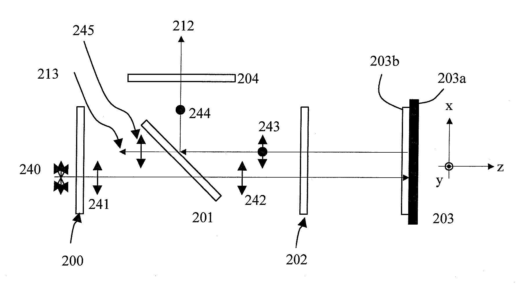
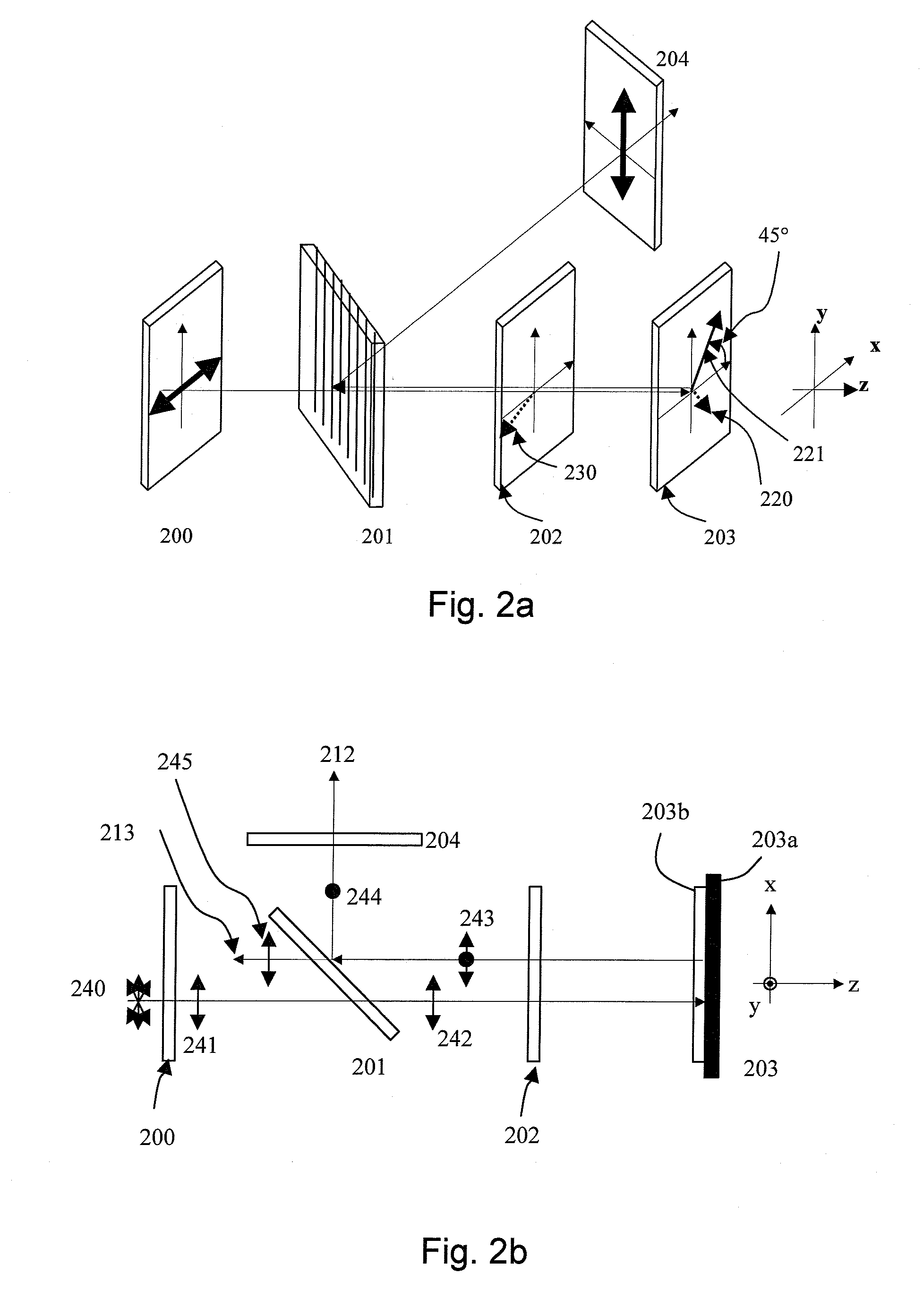
[0079] For the purpose of describing the instant invention, selected optics from one color-channel of a WGP-based LCoS microdisplay system, such as the one illustrated in FIG. 1, will be discussed in further detail. Referring to FIGS. 2a and 2b, these optics form a subsystem including a pre-polarizer 200, a WGP 201, a trim retarder 202, a VAN-mode LCoS panel 203, and a clean-up polarizer 204.

[0080] The pre-polarizer 200 is a polarizer oriented to transmit P-polarized light (e.g., which is shown as a horizontal double-sided arrow). According to one embodiment, the pre-polarizer includes one or more stages of substantially parallel elements of grid-based (reflective) polarizers (e.g., aluminum wiregrid) or regular dichroic sheet (absorptive) polarizers.

[0081] The WGP 201 is a polarizer formed from a plurality of parallel micro-wires disposed on a transparent substrate, as is well known to those skilled in the art. The WGP 201 is oriented such that its transmission axis is substantia...


PUM

PropertyMeasurementUnit
azimuthal angleaaaaaaaaaa

Abstract

A trim retarder for a liquid crystal display based projection system including a light source, a polarizer / analyzer, a liquid crystal display panel, and a projection lens, is clocked to an optimal azimuthal angle that provides a system contrast level substantially unaffected by the orientation of the slow axis of the liquid crystal display panel.

Description

CROSS-REFERENCE TO RELATED APPLICATIONS [0001] This application claims priority from U.S. Provisional Application Nos. 60 / 715,829 filed Sep. 9, 2005 and 60 / 737,113 filed Nov. 16, 2005, both of which are hereby incorporated by reference. This application is related to U.S. patent application Ser. Nos. 11 / 009,476 filed on Dec. 10, 2004 and 11 / 419,872 filed May 23, 2006, both of which are hereby incorporated by reference.MICROFICHE APPENDIX [0002] Not Applicable. TECHNICAL FIELD [0003] The present application relates generally to polarization compensation for projection displays, and in particular, to optimally clocked trim retarders and LCD-based projection systems including the same. BACKGROUND OF THE INVENTION [0004] Liquid-crystal displays (LCDs) are widely used in projection displays for large screen televisions and monitors. In these LCD-based projection systems, a high power beam of light is passed through a polarizer before being incident on a LCD panel. The LCD panel controls ...

Claims


Application Information

Patent Timeline
Patent Type & Authority Applications(United States)
IPC IPC(8): G02F1/1335
CPCG02B5/3058G02B5/3083G02F1/133632G02F1/133634G02F1/136277H04N9/3197G02F2203/02G02F2413/10H04N9/3105H04N9/3167G02F1/1393
Inventor TAN, KIM LEONGMACHE, ANTHONY JAMES JR.
Owner VIAVI SOLUTIONS INC
Learn More