
Apparatus and method for controlling internal combustion engine

a technology of internal combustion engine and apparatus, which is applied in the direction of combustion engine, electric control, machines/engines, etc., can solve the problems of difficult to avoid an increase in nox in the exhaust, and achieve the suppression of torque variation upon switching and deterioration of exhaust emission

Active Publication Date: 2007-03-22
HITACHI LTD
View PDF5 Cites 5 Cited by
  • Summary
  • Abstract
  • Description
  • Claims
  • Application Information

AI Technical Summary

Benefits of technology

[0006] In order to reduce NOx in the exhaust, a catalytic converter for leaning NOx is required, so that increase of the cost is not avoided.
[0007] It is an object of the present invention to provide an apparatus and a method for controlling an internal combustion engine capable of suppressing any of variation in torque and deterioration of exhaust emission suitably upon switching the combustion mode from the spark ignition combustion mode to the compression ignition combustion mode.
[0017] According to the control apparatus and the control method of the present invention, since control for continuing the spark ignition combustion mode is performed even when the operation conditions fall within the previously set compression ignition operation area upon switching of combustion from the spark ignition combustion mode to the compression ignition combustion mode, torque variation upon switching of combustion from the spark ignition combustion mode to the compression ignition combustion mode is reduced and deterioration of exhaust emission is also suppressed.

Problems solved by technology

In the above prior-art technique, even if the variation in torque can be suppressed by performing the stratified charge combustion mode upon switching the combustion mode of the spark ignition and the compression ignition, it is difficult to avoid an amount of NOx in the exhaust from being increased.

Method used


Image

  • Apparatus and method for controlling internal combustion engine
  • Apparatus and method for controlling internal combustion engine
  • Apparatus and method for controlling internal combustion engine

Examples


Embodiment Construction

[0025] Embodiments of a control apparatus of an internal combustion engine according to the present invention are now described with reference to the accompanying drawings.

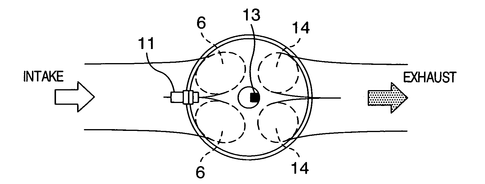
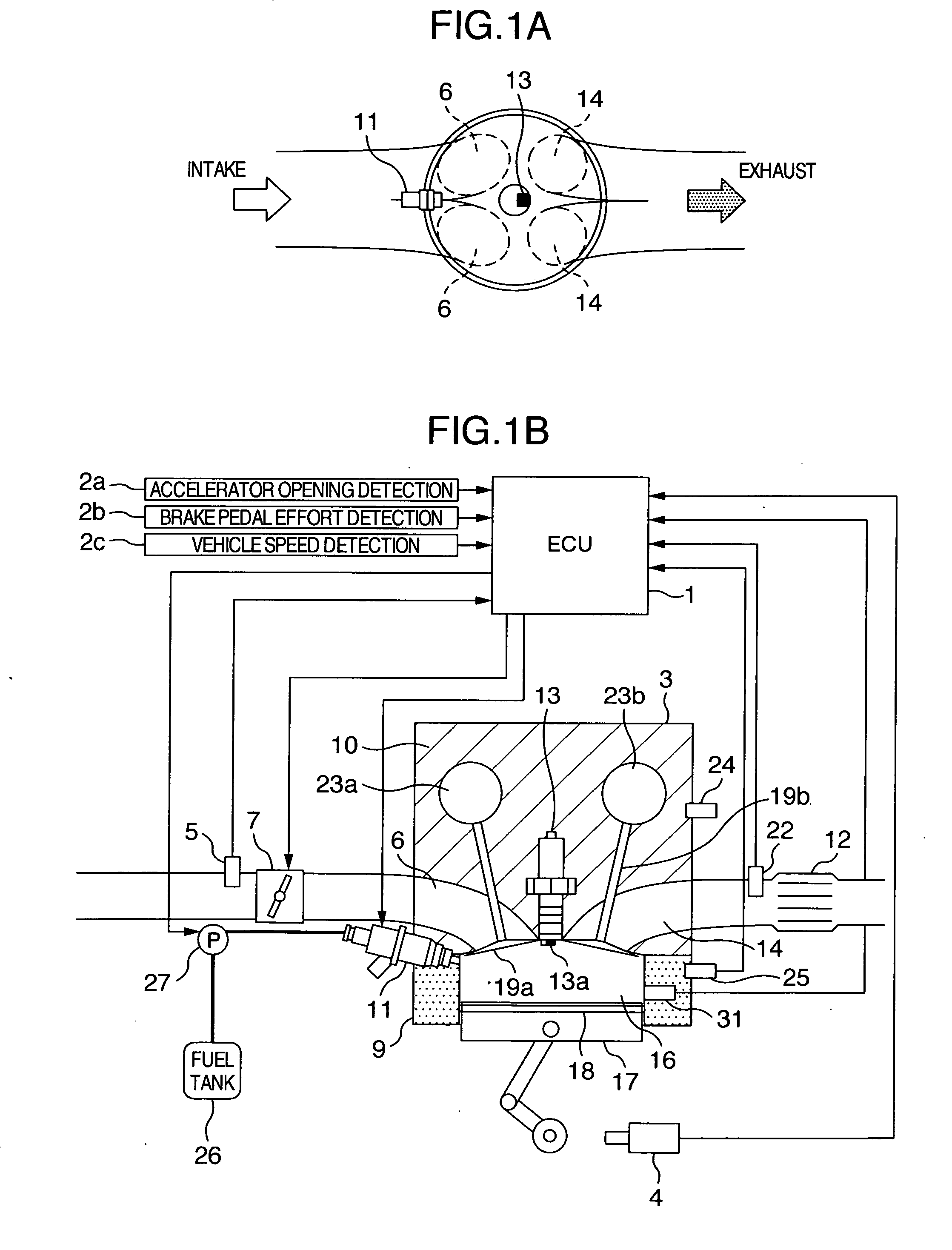
[0026]FIGS. 1A and 1B illustrate an embodiment of an internal combustion engine of a combustion mode switching type of spark ignition combustion and compression ignition combustion to which the control apparatus according to the present invention is applied.

[0027] An internal combustion engine 3 includes a combustion chamber 16 defined by a cylinder block 9, a piston 17 and a cylinder head 10. When the internal combustion engine is a multi-cylinder internal combustion engine, a plurality of combustion chambers 16 are formed. An intake port 6 and an exhaust port 14 communicating with the combustion chamber 16 for each cylinder are formed in the cylinder head 10. In the embodiment, the internal combustion engine 3 is a four-port-cylinder internal combustion engine including two intake ports 6 and two exhaust ports...


PUM


Abstract

A control apparatus of an engine having a compression ignition combustion mode and a spark ignition combustion mode selects the spark ignition combustion mode when operation conditions fall within a spark ignition operation area set in a spark ignition operation area / compression ignition operation area setting map memory part and selects the compression ignition combustion mode when the operation conditions fall within a switching stable area set in the memory part upon operation by the spark ignition combustion mode. The control apparatus controls to continue the compression ignition combustion mode as long as the operation conditions fall within a compression ignition operation area set in the memory part upon operation by the compression ignition combustion mode.

Description

BACKGROUND OF THE INVENTION [0001] The present invention relates to an apparatus and a method for controlling an internal combustion engine in which a spark ignition combustion mode and a compression ignition combustion mode are switched in accordance with operation conditions and more particularly to such control apparatus and method suitable for control of switching the combustion mode from the spark ignition combustion mode to the compression ignition combustion mode. [0002] In a gasoline engine, there is known an internal combustion engine in which the spark ignition combustion mode in which an air-fuel mixture is spark-ignited by means of an igniter and the compression ignition combustion mode in which the air-fuel mixture is self-ignited by piston compression are switched in accordance with operation conditions. [0003] In the internal combustion engine of the compression ignition combustion system adopting the combustion system in which the air-fuel mixture is compressed to be...

Claims


Application Information

Patent Timeline
Patent Type & Authority Applications(United States)
IPC IPC(8): F02B17/00F02B5/00F02B1/12
CPCF02B11/00F02D41/3064F02D41/3035Y02T10/12
Inventor YAMAOKA, SHIROKAKUYA, HIROMUSUZUKI, KUNIHIKOSATOU, SHINYASHIMADA, ATSUSHI
Owner HITACHI LTD
Learn More